The solution is to buzz the connections with a DMM, hello.
As to the provenance of the device in question, just try it, if it works correctly does it actually matter.
Dan.
Would you mind elaborate how? and what to look for? Continuity?
Check continuity from dip Pin1 to soic Pin1 ?
Similarly for pins 4 & 7
If necessary scrape off the painted pin numbers and paint on a new white dot.
Yup. Only if I can confirm which pin on the chip is pin 1
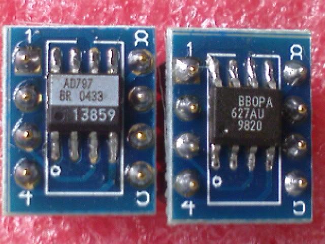
I think you did it correctly. Pin 1 is referenced to bottom left of chip if you can read text. A quick google image searches turned this up. Looks same as your orientation.

Very nice opamp BTW.
http://www.analog.com/media/en/technical-documentation/data-sheets/AD797.pdf
Hi, X
The item in question is not the same as you showed. There is no dot marking pin 1. I took the approach you mentioned (using the text/marking). I do not have any knowledge/experience of this item, thus the question.
I'm assuming he means on the adapter only.Yup. Only if I can confirm which pin on the chip is pin 1
The soic device is rotated to allow it to fit between the dip pins.Is there any need to rotate the device by 90 degrees? As far as I know, pin sequences are the same both in DIL-8 and SOIC-8 ICs?
Best regards!
There are some adaptors that place the soic outside the dip pin group and run long traces to interlink the pins.
Check continuity from adaptor pin1 to chip pin1, etc.Would you mind elaborate how? and what to look for? Continuity?
Dan.
he was told in post16Check continuity from adaptor pin1 to chip pin1, etc.
Dan.
Check continuity from dip Pin1 to soic Pin1 ?
Similarly for pins 4 & 7
By looking closely once again at the picture in the opening post it looks like the chip is oriented correctly since it has its beveled edge facing bottom and there is a more or less clearly visible trace from pin 1 of the adapter to what should be pin 1 of the chip (according to the beveled edge position). The problem I see with the chip is the missing dent/dot indicating pin 1 which probably means that the old part number has been mechanically polished off and the new marking (fake) has been printed. As already suggested earlier in this thread it's safer to throw it away then to try to make use of it without confidence, especially when it comes to such a part as AD797, IMO.
There are a few different ways it is done, but in each case it is obvious which one is pin 1. Dot, cut corner, beveled edge, small indent at the pin position, etc. So even if you don't know what a particular manufacturer uses, it is always pretty obvious which one is pin 1 or which is the side with pin 1 on it, which gives the same result. Stop worrying ;-)
Jan
Jan
My favorite adapters are these from Aries 08-350000-11-RC. Straight across so shortest trace length. Expensive though.
Sent from my iPhone using Tapatalk
Sent from my iPhone using Tapatalk
Hi, X
The item in question is not the same as you showed. There is no dot marking pin 1. I took the approach you mentioned (using the text/marking). I do not have any knowledge/experience of this item, thus the question.
I am not referencing dot - picture happens to have it. Just go by text if readable (not upside down) then pin 1 is bottom left.
I am not referencing dot - picture happens to have it. Just go by text if readable (not upside down) then pin 1 is bottom left.
Well, that's what I had done. Unfortunately, from what I found out so far, there seems to be no universal convention and could vary from manufacturer to manufacturer. Anyway, I shall find out 😛
Regards,
There are a few different ways it is done, but in each case it is obvious which one is pin 1. Dot, cut corner, beveled edge, small indent at the pin position, etc. So even if you don't know what a particular manufacturer uses, it is always pretty obvious which one is pin 1 or which is the side with pin 1 on it, which gives the same result. Stop worrying ;-)
Jan
Jan,
Without knowing much (all I know was the dot before this occasion arose), I assumed that when the text/marking is oriented properly (not upside down), the pin on the lower left hand corner would be pin 1. I made that assumption because many manufacturers kind of adopt this convention. I went back and check. Indeed, the "lower" edge (when the text/marking is oriented properly) is slightly beveled. So I think I guessed correctly.
Now I learn a little more about opamps 😛
Regards,
The convention is the beveled edge as the reference for the pin 1 side.from what I found out so far, there seems to be no universal convention
They all follow it.
The dot, the "U" shape at the end are optional and change based on the packaging house molds.
I am looking at the drawing for a LM4562D, it shows the index area, but does not specify exactly what is placed in the index area.
If you look at the package drawing, they usually reference a JEDEC package that is the industry standard.
In this case for a 8 pin soic with 50mil pin spacing, it MS-012 variation AA.
Sometimes the data sheets editors forget this reference, but it is basically implied and a well known fact.
Mmmm, AD797, 110MHz GBW, known temperamental opamp, on a SOIC adapter, then on a socket... what could possibly go wrong...
If it doesn't oscillate, maybe you got lucky and got a RC4558 with the serial numbers filed off...
If it doesn't oscillate, maybe you got lucky and got a RC4558 with the serial numbers filed off...
- Status
- Not open for further replies.
- Home
- Amplifiers
- Solid State
- Opamp orientation?