Hi folks
I hope someone can help me out. I have soldered a bunch of soic opamps onto "brown dog" pads so that they can be used with regular DIP opamp sockets. I would be grateful if someone can confirm that the orientation of the opamp wrt to the pin arrangement on the pad is correct. Or I am off by 180 degree. Yeah, I have should have asked before soldering 😱
Thanks!
Regards,
Attachments
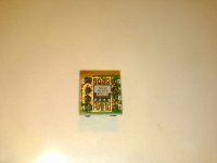
if someone can confirm that the orientation of the opamp wrt to the pin arrangement on the pad is correct.
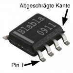
There should be a dot at pin 1. Are you sure this is a genuine device?
The markings do not seem right.
There should be a dot at pin 1. Are you sure this is a genuine device?
The markings do not seem right.
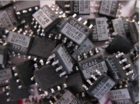
I could not find any dot on any of the pins of the chip. Thus the question. These were given to me and the person gave it away for exactly the same reason. I figure that I give it a try to see whether these would work. I have done some searching on Internet but it is not easy to distinguish the identity purely based on markings.
Regards,

Thanks for that link.
Thanks for that link.
You're welcome. 🙂
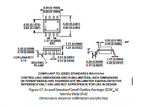
Btw, AD797 datasheet, page 18 outline dimensions, shows the beveled edge.
You're welcome. 🙂
Btw, AD797 datasheet, page 18 outline dimensions, shows the beveled edge.
Well, on the data sheet provided by AD (p 18.), the pin 1 in the drawing (for soic package) was clearly marked by a dot (lower left corner). So there is no ambiguity. No need to look for beveled edge. Since there is no standard practice to label pin 1, every manufacturer pick their own way. To be safe, one has to check the data sheet to confirm. If not one is just guessing.
There is one more pin 1 position marker on SOIC packages. In the attachment, although written in German, there is a clearly visible cut edge.
Again, this is the practice from one particular manufacturer and is explained in their literature I presume. I am not sure it is applicable to all other soic chips? Please correct me if I am wrong
Well, I guess the sure fire way is to put it in the circuit, fire it up and see whether it blow 😛

A genuine AD797 comes only from Analog Devices, since it's their unique part number and whatever their SOIC packages feature should always apply. Fakes and knock-offs are another matter, of course.Again, this is the practice from one particular manufacturer
Consider though, if you have what seems to be a fake or at least a non-genuine part, why would you play with it anyway? You may find it works just fine but its ultra-low noise capability may just not be feasible in your application so you may never realise that an NE5534 might have done just as well or better. I suspect though, that this more about perceived sound effects and rolling op-amps for fun.
Attachments
Last edited:
According to the Brown Dog website your orientation is wrong.
Clearly his adapters aren't from Brown Dog. They look like Chinese adapters, but should work just as well.
I think it's pretty safe to assume his 797s are Chinese fakes since I don't think anyone would give away a bunch of ICs worth about $10 a piece.
All the ones I've purchased have a dot at pin 1.
The solution is to buzz the connections with a DMM, hello.
As to the provenance of the device in question, just try it, if it works correctly does it actually matter.
Dan.
As to the provenance of the device in question, just try it, if it works correctly does it actually matter.
Dan.
Check continuity from dip Pin1 to soic Pin1 ?
Similarly for pins 4 & 7
If necessary scrape off the painted pin numbers and paint on a new white dot.
Similarly for pins 4 & 7
If necessary scrape off the painted pin numbers and paint on a new white dot.
Last edited:
I think you did it correctly. Pin 1 is referenced to bottom left of chip if you can read text. A quick google image searches turned this up. Looks same as your orientation.

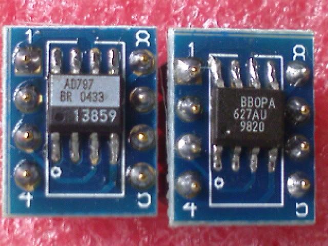
Very nice opamp BTW.
http://www.analog.com/media/en/technical-documentation/data-sheets/AD797.pdf
Very nice opamp BTW.
http://www.analog.com/media/en/technical-documentation/data-sheets/AD797.pdf
Last edited:
This is different from post12I think you did it correctly. Pin 1 is referenced to bottom left of chip if you can read text. A quick google image searches turned this up. Looks same as your orientation.
Is there any need to rotate the device by 90 degrees? As far as I know, pin sequences are the same both in DIL-8 and SOIC-8 ICs?
Best regards!
Best regards!
why would you play with it anyway?
Curiosity. Use this as a learning opportunity.
- Status
- Not open for further replies.
- Home
- Amplifiers
- Solid State
- Opamp orientation?