I'm a little younger - uni lectures end of the last millenium 😀
Annoyingly, I've realised I'm short of a 2x7way 0.1" IDC connector so I can't do my testing yet. I've never found a way to undo one of those without breaking the tabs on the end (I have a few I could recycle). And I don't think I can find a shop locally (Reading) with them in stock. Maplins are totally useless nowadays 🙁
Ahh sod it, I've broken one, but it will have to do!
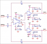
Is this what you need, you could maybe just use the front stage, I like the sound of AD825 though.
Cheers George
Cheers George
Attachments
Last edited:
Thanks George, and sorry for not replying sooner.
I'm now working a bit more on this and using the second design as a base (looks like it's the one from the LM47924 datasheet).
One of the challenges I'm seeing is at this level of performance, very small things come into effect like using really small and very closely located decoupling caps to minimise inductance of traces, etc. Combine that (which really means SMD components) with the 47924 which is only available surface mount and it becomes tricky to prototype without resorting to designing a PCB. It also makes swapping components / trialling different combinations tricky if it's not on a breadboard...
I'm working on a PCB now for this and it's very similar to how Hypex have designed their adapter prototyping board for the Ncore500 which I bought to test with.
Also, for power requirements, I'm using their SMPS which has a few auxiliary voltage outs you can piggy back on, and the best bet looks like using their unregulated +/- output (around +/-23V) which I can easily regulate down to 15V to power opamps and related circuitry upstream of the main Ncore amp.
Last edited:
I'm still getting my head around the balanced Opamp circuit

The 68pF caps in the feedback loop are to filter out any DC component?
The overall differential gain is 2x[(18k+1.5k)/1.5k] ?
The 2.2nF caps are there for what exactly? I presume they're more linked to the presence of the DAC upstream rather than a requirement for the Opamp as the latter's datasheet circuit that georgehifi posted doesn't show them?
to apply some HF feedbackI'm still getting my head around the balanced Opamp circuit
The 68pF caps in the feedback loop are to filter out any DC component?
18k/1.5kThe overall differential gain is 2x[(18k+1.5k)/1.5k] ?
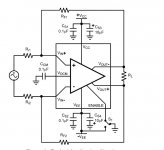
RF interference attenuation.The 2.2nF caps are there for what exactly?
I presume they're more linked to the presence of the DAC upstream rather than a requirement for the Opamp as the latter's datasheet circuit that georgehifi posted doesn't show them?
Thanks Andrew.
18k/1.5 is that per leg or total differential?
What I'm trying to do is understand the differences between the balanced version and the non-balanced version which is a lot simpler.
18k/1.5 is that per leg or total differential?
What I'm trying to do is understand the differences between the balanced version and the non-balanced version which is a lot simpler.
apply 1V to +IN and you get 12V @ +OUT.
apply 1V to -IN and you get 12V @ -OUT.
apply 2V across +IN/-IN and you get 24V between +OUT and -OUT.
apply 1V to -IN and you get 12V @ -OUT.
apply 2V across +IN/-IN and you get 24V between +OUT and -OUT.
Thanks, but isn't it inverting, i.e. the voltage on the +IN is amplified and comes out at the -OUT and vice versa?
Over both inputs it doesn't matter I guess, except that it's an inverted amplified signal, i.e. 2V between +IN/-IN gives you -24V between +OUT/-OUT (or +24V between -OUT/+OUT)
Over both inputs it doesn't matter I guess, except that it's an inverted amplified signal, i.e. 2V between +IN/-IN gives you -24V between +OUT/-OUT (or +24V between -OUT/+OUT)
Hi all, I want to use this LME49724 buffer as input stage of my UCD400 OEM modules which also can be driven unbuffered. They require 9Vrms level to be 100% driven. If I'm going to feed it from another source, which resistor value can I change to lower the gain with factor of 2x? Can it be driven from single ended output from Soekris R2R DAC? It has 1.4Vrms level.
Last edited:
Since this design is a filter and is differential there's no one resistor that can simply be changed which leaves the same frequency response. You'd need to change two resistors and two capacitors. At a guess increase the 1k5s to 3k and the 2n2s reduce to 1n, but this is just a guess.
- Status
- Not open for further replies.
- Home
- Source & Line
- Analog Line Level
- Opamp input buffer choices