Hi Simon,
Yeah, that is what I was thinking, but not knowing the origins of the design. Leaving the op amp of the day a touch into class A may have really helped at low levels.
This could be an interesting headphone amplifier by adding an MPSA06 and 56 as drivers in a diamond configuration with a pair of TO-126 outputs. What do you think? The OPA2134 would be justified then. It would be a shame to see that driving a mystery speaker though! 🙂
I'm glad you found that link. A picture is worth 1,000 words!
-Chris
Dear Chris:
I will use the chipamp TDA2030. (I have already bought them)
I just need max 2 watts for my speaker.
I will work with about 120 SPL
I will use the speaker to send a pulse signal and test the microphone polarity.
My power supply has 8 volts and the input sinewave comes from my computer sound cards (Line out.)
The speaker is enclosed and it is HIFI (8 ohm) with 2.5 inches aprox of cone.
The TDA2030 is like a power version of an opamp...
Thank you for your help.
Regards.
Alfredo Mendiola Loyola
Lima, Peru
Attachments
Last edited:
Hello sreten. I hope that I am not complicating this matter. I remembered the encircled schematic from a 1976 National Linear Data Book. I thought it maybe adapted to the schematic of amendiola in post #1. It is old-fashioned and is superseded by other improved methods to bias the power output transistors as per the post of simon7000.Hi,
Sorry but that is just plain wrong.
rgds, sreten.
Best regards
Attachments
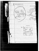
Hello sreten. I hope that I am not complicating this matter. I remembered the
encircled schematic from a 1976 National Linear Data Book. I thought it maybe
adapted to the schematic of amendiola in post #1. It is old-fashioned and is
superseded by other improved methods to bias the power output transistors
as per the post of simon7000.
Best regards
Hi,
Note the actual value is 5R not 50R. It has no effect on DC bias.
I have no idea what useful purpose it serves, it looks very wrong.
(edit : it could force a crude form of current limiting of the output,
by assumed output device hfe and the op-amps current limiting.)
rgds, sreten.
Last edited:
Hello sreten. I hope that I am not complicating this matter. I remembered the encircled schematic from a 1976 National Linear Data Book. I thought it maybe adapted to the schematic of amendiola in post #1. It is old-fashioned and is superseded by other improved methods to bias the power output transistors as per the post of simon7000.
Best regards
That is actually an AB + B amplifier. The op amp provides the power for low level signals and the output transistors only kick in when the current demands go above about 10 mA.
- Status
- Not open for further replies.