Your output impedance will be low to very low. You do need to set up some bias current for the output transistors or the amplifier will not sound very good, especially at low volume levels. The op amp can reduce crossover distortion, but it can't eliminate it with that setup.
The exact output impedance will change near the zero point, it isn't constant. But, this is unimportant. Your speaker will be a much higher impedance than the output stage. Given this very simple circuit, you are wasting an OPA2134. You could use an NE5534A and still have a far better op amp than the circuit needs. With some bias current in the output stage, a 4556 op amp might work better as it has better output drive. The slew rate would not be an issue unless you leave that output stage as it is.
This is a learning experience for you. What are you planning to drive with this amplifier?
-Chris
I want to drive a 8 ohm speaer to test my microphones. I use an oscilloscope to review the sine wave.
I want to amplify sine audio frequency.
My opa2134 can't load my speaker...
Thank you.
I want to amplify sine audio frequency.
My opa2134 can't load my speaker...
Thank you.
Hi Alfredo,
So this is an instrumentation amplifier. You must use some bias current for the outputs. Otherwise it will sound like a defective speaker.
You will end up with a positive damping factor, meaning the amplifier will be able to control the speaker. This is what you want. If not, then you must drive the speaker with a current source. This introduces other issues you would need to deal with in some way. A low damping factor will also help to maintain a more constant output level, but there is no way for you to know how much acoustic power you are generating without first calibrating your test setup with a calibrated microphone / amplifier first.
Will you be using a small enclosed chamber, or a large test chamber? Do you have a noise source designed for testing microphones (you could then roughly calibrate your own microphones)? Now I am trying to figure out why you are attempting to use this amplifier design when almost anything produced commercially has much better performance. I know that isn't what you wanted to hear - sorry. But I would rather you didn't find out later that you wasted a great deal of time.
-Chris
Hi Alfredo,
So this is an instrumentation amplifier. You must use some bias current for the outputs. Otherwise it will sound like a defective speaker.
You will end up with a positive damping factor, meaning the amplifier will be able to control the speaker. This is what you want. If not, then you must drive the speaker with a current source. This introduces other issues you would need to deal with in some way. A low damping factor will also help to maintain a more constant output level, but there is no way for you to know how much acoustic power you are generating without first calibrating your test setup with a calibrated microphone / amplifier first.
Will you be using a small enclosed chamber, or a large test chamber? Do you have a noise source designed for testing microphones (you could then roughly calibrate your own microphones)? Now I am trying to figure out why you are attempting to use this amplifier design when almost anything produced commercially has much better performance. I know that isn't what you wanted to hear - sorry. But I would rather you didn't find out later that you wasted a great deal of time.
-Chris
If there is an opamp with low output impedace that can drive a 8 ohm load with the same quality of the opa2134 i will use it.
Regards.
Hi Alfredo,
Well, the point is that you will not see the quality of the op amp you are using with that circuit. Because your output transistors do not have any idle bias, there is a discontinuity in any output waveform that will look like a damaged transducer, like a voice coil that sticks in the center position. Your circuit is too simple to do what you are asking of it.
Have you tried to build this circuit and try it?
One thing I am unsure of is what you mean by "
My opa2134 can't load my speaker...". Could you elaborate on that please?
-Chris
Hi Alfredo,
Okay, that is much more clear. What we would normally say is that the OPA2134 can't drive low impedance speakers. You can get communications speakers at 600 ohms. At that impedance, the NE5534 / NE5532, the 4556 and maybe even the OPA2134 could drive that load directly. A TL071 would not be a good choice.
If you went that route, the NJM4556 would be the best choice. I doubt you need a very low noise device for that duty. Depending on how loud you want this to be, a normal op amp might be fine.
When you use the word "load", to this engineering area it means that the OPA2134 (in this case) is acting as a load, not as a source. Loads utilize energy, or dissipate it as heat. A source to you might be the output of a sound card, or an oscillator. But to the speaker, the op amp is the source. Terminology can make things confusing if it isn't spot on.
Do you think using a 600 ohm speaker might be an option for you?
-Chris
Hi Alfredo,
Okay, that is much more clear. What we would normally say is that the OPA2134 can't drive low impedance speakers. You can get communications speakers at 600 ohms. At that impedance, the NE5534 / NE5532, the 4556 and maybe even the OPA2134 could drive that load directly. A TL071 would not be a good choice.
If you went that route, the NJM4556 would be the best choice. I doubt you need a very low noise device for that duty. Depending on how loud you want this to be, a normal op amp might be fine.
When you use the word "load", to this engineering area it means that the OPA2134 (in this case) is acting as a load, not as a source. Loads utilize energy, or dissipate it as heat. A source to you might be the output of a sound card, or an oscillator. But to the speaker, the op amp is the source. Terminology can make things confusing if it isn't spot on.
Do you think using a 600 ohm speaker might be an option for you?
-Chris
I want to use my 8 ohm speaker, it has a cone with 10cm of diameter. I don't want to buy a new speaker.
Thank you
Alfredo
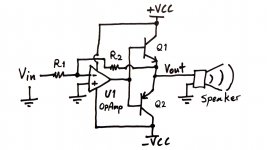
Hello amendiola. Put a 50 Ohm resistor between Vout and the output of the Op Amp so as to minimize x-over distortion. Initially, the Op Amp supplies +/-12mA to the load. This current when multiplied by 50 Ohms then gives ~+/- 0.6V which is the forward bias needed to turn on the output transistors. They take over to deliver power output after they turn on.I want to drive a 8 ohm speaer to test my microphones. I use an oscilloscope to review the sine wave.
I want to amplify sine audio frequency.
My opa2134 can't load my speaker...
Thank you.
Hi Antoinel,
That may not be enough to avoid x-over distortion. He really needs a bias control circuit from what he tells us what he wants to do. Most op amps can't deliver enough current during the time the outputs are off, and there are out of phase currents that are definitely beyond an op amp.
-Chris
That may not be enough to avoid x-over distortion. He really needs a bias control circuit from what he tells us what he wants to do. Most op amps can't deliver enough current during the time the outputs are off, and there are out of phase currents that are definitely beyond an op amp.
-Chris
amplifier - Reducing noise in an audio amplifer using opamp - Electrical Engineering Stack Exchange
The second schematic shows how to bias.
The second schematic shows how to bias.
Hi Alfredo,
How loud do you need this to be? Do you have an SPL in mind here? How flat does your response from the amp / speaker have to be?
You haven't set out the parameters you need to meet yet. It is very possible that under a non-existent budget you will never meet your goals. It's clear you will have to throw some money at this problem, because what you describe cannot be done very well with what you have showed us so far.
So. Is this speaker enclosed or not? Is it a communications speaker, a hi fi speaker or one released from something like a television or radio? Is it a quality speaker with a make and model? How much do you know about it?
Also. Are you fixed on using the circuit you proposed, or are you willing to build / buy something that will do the job?
Finally. How loud will this have to be? How much power do you need (easy to figure out from the efficiency of the speaker and your required loudness)? We need this information in order to help you.
-Chris
Hello amendiola. Put a 50 Ohm resistor between Vout and the output of the
Op Amp so as to minimize x-over distortion. Initially, the Op Amp supplies
+/-12mA to the load. This current when multiplied by 50 Ohms then gives
~+/- 0.6V which is the forward bias needed to turn on the output transistors.
They take over to deliver power output after they turn on.
Hi,
Sorry but that is just plain wrong.
rgds, sreten.
Hi Simon,
Exactly! +1
The article also reminds us of the 4556 which I mentioned earlier as being more suitable.
Question for you Simon. I have seen this circuit many times. Why don't they drive the outputs from the center point of the two diodes? Shouldn't there be a capacitor across the diode pair? (0.47 uF to 10 uF)
Hi Alfredo,
The second circuit has the best chance of doing what you want. We still don't know what your expectations are for the amplifier circuit.
-Chris
Hi Simon,
Exactly! +1
The article also reminds us of the 4556 which I mentioned earlier as being more suitable.
Question for you Simon. I have seen this circuit many times. Why don't they drive the outputs from the center point of the two diodes? Shouldn't there be a capacitor across the diode pair? (0.47 uF to 10 uF)
Hi Alfredo,
The second circuit has the best chance of doing what you want. We still don't know what your expectations are for the amplifier circuit.
-Chris
Probably either because when the circuit first appeared the lateral PNP output stage gave a slight benefit to the asymetric drive or it actually leaves a bit of bias going at zero output to keep a class B opamp in Class A at the zero crossing.
With the inherent distortion of the older opamps it probably wasn't worth the extra part.
Hi Simon,
Yeah, that is what I was thinking, but not knowing the origins of the design. Leaving the op amp of the day a touch into class A may have really helped at low levels.
This could be an interesting headphone amplifier by adding an MPSA06 and 56 as drivers in a diamond configuration with a pair of TO-126 outputs. What do you think? The OPA2134 would be justified then. It would be a shame to see that driving a mystery speaker though! 🙂
I'm glad you found that link. A picture is worth 1,000 words!
-Chris
- Status
- Not open for further replies.
- Home
- Amplifiers
- Solid State
- Opamp Class B amplifier output impedance