Hello,
I'm looking for IEM models to drive with an op-amp with a maximum output current of 45mA (AD4075-2). My source signal is max. 1.5V-peak, so I assume that the ideal load impedance would be 33ohms (1.5/0.045) .
Does it make a difference to have impedance matched cans in general, striving for minimal voltage-to-current conversion? I've read that at the end only power matters. If the cans are low in impedance, the excess of voltage from the amplifier will be converted into current. But I like the idea of listening to a voltage swing that replicates that of the output signal from the amplifier.
I ask this because IEMs are normally very low impedance (ie. 16ohm), it is quite challenging to find anything around 32ohms and maybe I'm giving importance to something that is not really important at the end.
I'm not sure also what the target SPL should be. I guess around 114dBSPL is already painful enough? In that case I would be looking for 96dB/mW IEMs (non-existent). But I'm lost there. Is it better to look for higher sensitivity IEMs to minimize current load on the opamp (which could maybe decrease current noise), or minimum sensitivity IEMs to increase the output current into the monitors (which could translate in higher fidelity or detail).
A lot of assumptions here. All certainties or opinions will be welcome forever.
–Domingo
Most opamps will have rapidly rising output distortion with loads below 600 ohms, something to watch out for (the lower the signal swing the less severe, but its still something to consider).
The normal approach is add a current buffer on the output of the opamp within the feedback loop - job done.
The normal approach is add a current buffer on the output of the opamp within the feedback loop - job done.

Thanks for the tip @Mark Tillotson!
Do you mean to add a transistor at the opamp‘s output? Or a proper buffer IC?
I didn‘t know about distortion with high loads 🙂 If you have any schematic to suggest I‘d appreciate it!
–Domingo
Do you mean to add a transistor at the opamp‘s output? Or a proper buffer IC?
I didn‘t know about distortion with high loads 🙂 If you have any schematic to suggest I‘d appreciate it!
–Domingo
The LT1010 buffer chip is available in a thru hole package. I found the schematic below on reddit.com in a thread called "A Pretty Decent Headphone Amplifier". It uses a pair of LT1010s {2 x 150 mA !} per channel ; I have no idea whether the circuit sounds great or works well. But here's the schematic.
_
_
Attachments
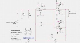
Yei thank you! Did they forget the output cap at the output? Or this implementation need somehow none 🙂?
Last edited:
Yes @bansuri, that model looks really nice and not expensive. Thing is, I need this for serious audio signal monitoring, so I might be better looking for something able to drive 1.5V-peak at least–so the totality of the swing is reproduced.
I'm thinking of hiss for example. If impedance is too low, some of the noise in the source signal might disappear. If impedance is too high, I might start hearing noise produced by an excess of voltage. But I'd prefer to hear the actual noise or hiss in the source signal for instance, no more or less. 33ohms seem like the sweet point for 1.5V-peak I think. Bare with me if this is a wrong interpretation.
But thanks again for the recommendation! It seems anyways very attractive.
I found a Harman curve IEM (Moondrop Blessing 2) that seems to be 26 ohms according to user reports and not very sensitive (100.4dB/mW).
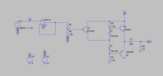
I designed a simple discrete AB amp for it, because I'm running on batteries. Distortion is a little high, between 1-2% on Spice. I had to include a buffer emitter follower between op-amp and the AB amp for volume control. The input signal is a DAC, so I couldn't put it before the op-amp.
Please feel free on any comments or suggestions. I haven't tried the circuit yet and I'm not all that knowledgable, so something relevant might be missing.
Attachments
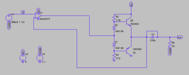
I tried enclosing the AB amp within the feedback loop and distortion went down to 0.04% 🙂
Is there any creative way to introduce volume control within the loop? I would much prefer to leave the second opamp for the second channel and keep it minimal/discrete.
Also, if I remove the output cap distortion goes down to 0.001. The question is then how to build a sturdy enough VGND for the phones to sit on.
Attachments
You could use the virtual ground approach, although I always use traditional single-supply designs with input and output caps for headphone drivers powered by a single 9V battery.
If it were me, I would include a trimmer so I could adjust the bias current through the discrete output stage. If you bias it at about 4.5mA then it will run class-A up to 100 dB for 26 Ohm 100 dB/mW phones. That is loud enough to permanently damage your hearing in short order. Of course you can use less bias current to prolong battery life.
For the volume control, the basic options are probably a logarithmic potentiometer before the opamp, or a linear potentiometer as part of the feedback network.
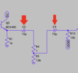
Below are a couple of examples, where I am assuming you do not want any voltage gain. There is nothing special about them - I am sure many improvements could be made. But they should work fine as long as the opamp is unity-gain stable. You could simplify the buffers below by eliminating the trimmer and C4 (and even R6), but I would suggest including the emitter resistors to avoid thermal runaway.


If it were me, I would include a trimmer so I could adjust the bias current through the discrete output stage. If you bias it at about 4.5mA then it will run class-A up to 100 dB for 26 Ohm 100 dB/mW phones. That is loud enough to permanently damage your hearing in short order. Of course you can use less bias current to prolong battery life.
For the volume control, the basic options are probably a logarithmic potentiometer before the opamp, or a linear potentiometer as part of the feedback network.
Below are a couple of examples, where I am assuming you do not want any voltage gain. There is nothing special about them - I am sure many improvements could be made. But they should work fine as long as the opamp is unity-gain stable. You could simplify the buffers below by eliminating the trimmer and C4 (and even R6), but I would suggest including the emitter resistors to avoid thermal runaway.
Last edited:
Dear @jasonRF,
I really appreciate taking the time to share your experience and knowledge with me.
How did you calculate this? 100dB/mW phones will shout 100dB at 1mW, which is not very loud right? That's why I'm biasing the ABamp transistors at around 200uA. Guessing 220hFE transistors, they would deliver 44mA on the output. 26 x 0.044^2 = 50mW. This should produce 117dBSPL on 100dB/mW phones, which I'm estimating as a bearable threshold of pain (maybe I'm wrong).
If the ABamp is biased at 4.5mA as you say, according to the same calculations the phones would produce 131dBSPL and everything including my head would explode. Just trying to understand what did you mean, I'm not so used to maths.
I really appreciate taking the time to share your experience and knowledge with me.
If you bias it at about 4.5mA then it will run class-A up to 100 dB for 26 Ohm 100 dB/mW phones. That is loud enough to permanently damage your hearing in short order.
How did you calculate this? 100dB/mW phones will shout 100dB at 1mW, which is not very loud right? That's why I'm biasing the ABamp transistors at around 200uA. Guessing 220hFE transistors, they would deliver 44mA on the output. 26 x 0.044^2 = 50mW. This should produce 117dBSPL on 100dB/mW phones, which I'm estimating as a bearable threshold of pain (maybe I'm wrong).
If the ABamp is biased at 4.5mA as you say, according to the same calculations the phones would produce 131dBSPL and everything including my head would explode. Just trying to understand what did you mean, I'm not so used to maths.
If you bias a class-AB output stage at 4.5 mA, it can deliver 9mA peak current to the load in class-A mode. So for a 26 Ohm load, the AC power delivered class-A will be 9e-3 * 9e-3 * 26 / 2 = 1e-3 W = 1mW. It can of course deliver much more current in class-AB operation.
Regarding the effects of listing at high SPL, it might be worth looking at
https://www.cdc.gov/nceh/hearing_loss/what_noises_cause_hearing_loss.html
Your 1.5V peak would be pretty dangerous to use with those phones.
I usually listen closer to 70 dB with 100 dB/mW phones, but try to design for good performance at 1mW so I have a lot of headroom, even if I eventually get phones that are more like 90dB/mW. But my 1mW number is arbitrary. One great thing about DIY is that you can customize for your own needs.
cheers,
jason
Thanks again Jason!
I'm still not fully clear on the correct values for the resistors at the base of the transistors of the ABamp (in series with the diodes). I measured with an oscilloscope different values on the ABamp alone, not enclosed yet inside the feedback loop, and the minimum resistor values to get a 1Vrms sinewave without distortion with a 26ohm output resistor was 1k (for both NPN and PNP).
If I try 4.7k as in your example I get a lot of distortion, but yes without enclosing it within the opamp's loop–the loop is complicated to prototype for me right now, I want to test it independently for a while until I print a new PCB.
Anyways, what would be the base resistor values to bias the output at 4.5mA, as you seem to recommend? If I simulate your schematic with 4.7k at the bases and without load, which I suppose is what you mean with bias current, I measure only 73uA from peak-to-peak. With 1k resistors I get little less than 1mApp.
Sorry for the long question, insistence and confusion. And thanks for the link to hearing loss. Very explicative. I read it thoroughly in the waiting room of a boring regular medical check, so I took it very seriously.
This schematic seems to work the best to me, due the circumstances.
The input is buffered because it is a DAC (w/ 5K output impedance). I place the volume potentiometer between DAC and the reconstruction filter, isolated with coupling caps.
Without the potentiometer I would save two caps and the buffer transistor, but can't find a more effective way to do it. Unless digital volume, but that's not possible for me currently.
Last edited:
Here I will refer to part numbers in the schematic in post 16. Also, when I have been referring to the bias int he output stage, it is the DC current through Q1 and Q2 when there is no AC signal present. This bias current is controlled by the voltage drop between the bases of Q1 and Q2. The distortion will be greatly effected by the output stage bias current. If it is too low then you will see a lot of crossover distortion.Thanks again Jason!
I'm still not fully clear on the correct values for the resistors at the base of the transistors of the ABamp (in series with the diodes). I measured with an oscilloscope different values on the ABamp alone, not enclosed yet inside the feedback loop, and the minimum resistor values to get a 1Vrms sinewave without distortion with a 26ohm output resistor was 1k (for both NPN and PNP).
If I try 4.7k as in your example I get a lot of distortion, but yes without enclosing it within the opamp's loop–the loop is complicated to prototype for me right now, I want to test it independently for a while until I print a new PCB.
For this experiment, did you include the extra trimmer resistor in series with the diodes D1 and D2? If not, then I am not surprised that you need R2 and R3 to be fairly low in order to get enough voltage drop across D1 and D2 to provide an acceptable bias current in Q1 and Q2. Without the trimmer and with R2=R3=1k, you probably have more bias current through D1 and D2 than you do in Q1 and Q2. For good battery life you will want to spend your current in the output stage (Q1 and Q2) where it has the most benefit for reducing distortion.
With the trimmer included, you can increase the DC voltage between the bases of Q1 and Q2, which is what increases the DC bias current through Q1 and Q2. In this case, you can have higher bias current in Q1 and Q2 than you do in D1 and D2, so you are spending your battery more effectively. The capacitor I added between the bases of Q1 and Q2 is really needed with the trimmer, though, so it adds another part. It helps a lot with reducing distortion.
I would set the current through D1 and D2 according to the maximum current you want to deliver to your load; for example, if you want 1V rms into 26 Ohms, then the peak current in the load is 1.414 V / 26 Ohms = 54 mA. If Q1 and Q2 have a gain of 100, then you need at least 0.54 mA bias in D1 and D2. In my example I made it a little higher at about 0.8 mA. With this current through D1 and D2, you then adjust the trimmer to get the desired bias current in Q1 and Q2. It can be fun to adjust the trimmer while looking at the signal on your scope or audio interface to see the distortion levels change.
Finally, I strongly suggest you include resistors between the emitters of Q1 and Q2. Without them the output stage can be thermally unstable, and it is possible to get a condition called thermal runaway. When this happens, the current through Q1 and Q2 keeps increasing and increasing until something bad happens. In my example I used 3.3 Ohms since I know for sure it will be very stable with a 9v battery. I have seen thermal runaway on the breadboard before - it isn't fun!
jason
Last edited:
I should add that you of course can eliminate the trimmer and the capacitor and keep your circuit as-is. You will just need to make the current through D1 and D2 higher (more current through the diodes increases the voltage across them) to get the output stage bias that you want for acceptable distortion levels. In this case I wouldn't be surprised if R2=R3 needs to be 1k or even smaller.
jason
jason
Thanks a lot @jasonRF. I think it is now very clear and I really like your design. I simulated it again and it draws much less power, especially when headphones are not plugged in. It makes all sense to direct current to the load as much as possible, I just have to include the extra parts for a future PCB design. At the moment I'm just trying to modify a board/device I made and I don't have much space there, but I'll basically follow your idea exactly when I start again. 👍👍
Why do you use a trimmer instead of a 330R resistor? Would it be to find a sweet spot, how do you determine it?
And a bit extra related but taking the chance that I've got your attention: My case space is quite limited for big output caps, but I also don't want to lose any hearable bass. I found some 1000uF 6.3V Panasonic FK-V caps that are about the max. size I can afford (8x10mm). Would you have a say on that?
Last edited:
Is there any way at all to get rid of the two capacitors in series? Maybe instead of two back-to-back 10uF polarized electrolytic capacitors in series, there might be some way to use a single 4.7 uF non-polarized capacitor? (Here is one) possibility at Digi-Key.
_
_
Attachments
- Home
- Amplifiers
- Headphone Systems
- opamp and IEMs: impedance matching and sensitivity