Hi guys,
hehe, this is my first post.
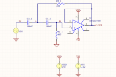
I am trying to design a HPF using the OPA627 op-amp.
I have simulated the design in Protel and ran simulation, however I am getting some weird results. (or so I think).
My HPF is supposed to be a 4kHz HPF.
The schematic & simulation plot is attached!
From my understanding of filters, the crossover point should be the -3dB point, right?
From the plots the -3db point is CROSSOVER/2 or 2kHz.
Also at the 4kHz point, the attenuation is -6dB.
Why is that?
hehe, this is my first post.
I am trying to design a HPF using the OPA627 op-amp.
I have simulated the design in Protel and ran simulation, however I am getting some weird results. (or so I think).
My HPF is supposed to be a 4kHz HPF.
The schematic & simulation plot is attached!
From my understanding of filters, the crossover point should be the -3dB point, right?
From the plots the -3db point is CROSSOVER/2 or 2kHz.
Also at the 4kHz point, the attenuation is -6dB.
Why is that?
Attachments
I guess you are trying to build a 2nd order Butterworth HP. Then you should double the value of some resistors and capacitors - can never remember which ones but you can either do the math or just look it up on any site. The Texas Instruments (http://www.ti.com) site has a Filter Wizard that relieves you of the work.
For most filter characteristics the cutoff point is specified as the -3 dB point. Not so for Linkwitz-Riley (two cascaded Butterworth stages, hence the name Butterworth-squared) where it is at -6 dB.
/Magnus
For most filter characteristics the cutoff point is specified as the -3 dB point. Not so for Linkwitz-Riley (two cascaded Butterworth stages, hence the name Butterworth-squared) where it is at -6 dB.
/Magnus
I used the formulas in the Texas instruments document "OPAMPS for everyone".
Are you saying those formulas are wrong?
Are you saying those formulas are wrong?
4th order Butterworth HPF
Which formulas would I need to use to design a 4th order Butterworth then?
Do I use the coefficients from the Filter Table ?
Which formulas would I need to use to design a 4th order Butterworth then?
Do I use the coefficients from the Filter Table ?
It was a while since I read that document, but for a 4th order Butterworth - yes I think the coefficients are in the table IIRC.
But why would you like to use a 4th order Butterworth for audio?
But why would you like to use a 4th order Butterworth for audio?
24db/octave
I like sharp cut-off curves. And a 24db/oct will provide that.
Or will it?
For example if I want to cut off my Subwoofer at 150Hz, I dont want to still play faint tunes at 500Hz.
What do you suggest?
I like sharp cut-off curves. And a 24db/oct will provide that.
Or will it?
For example if I want to cut off my Subwoofer at 150Hz, I dont want to still play faint tunes at 500Hz.
What do you suggest?
Yes, sharp cutoffs are good because they reduce the comb-filtering effect that results when more than one driver are playing the same signal. And they keep each driver in its best range (out of cone-breakup) and thus reduces distortion.
24 dB/oct is pretty much the gold standard for active filters.
But as good as the Butterworth response is for many engineering applications it is not ideally suited for audio active filters. If you add up the resultant acoustic output from an LP and HP Butterworth filter you will have a 3 dB bump in response at the crossover point. That is why you usually use a Linkwitz-Riley response which sums up flat and as a side bonus has a linear phaseshift between the LP and HP section. Thus they are also sometimes called "phaselinear" filters.
So there is no surprise that 99.9% of the (analog) active filters for audio on the market are LR... 😉
The LR transfer function is very easy to obtain as it is just composed of cascaded Butterworth stages. So a 4th order (24 dB/oct) LR is made by cascading two 2nd order Butterworth's with exactly the same component values. A dual opamp like the NE5532, AD8620, OPA2604, TL072 or whatever will do the trick for one channel.
Once you have gone active you will probably never look back to passive filters. There is a reason why active filters are the standard in all pro sound applications today with passive crossovers rapidly becoming obsolete. And there is a reason why the "audiophile" industry sticks to passive crossovers and exotic components. Feel free to choose. 😎
/Magnus
Ok, so lets say I go with a LR x-over.
Does that mean that if I wanted a x-over at 4kHz I should actually design the filter for a 8kHz crossover, therefore the 4kHz point happens at -3dB rather than -6dB?
Also, has anyone used UAF42, the TI Active Filter?
Does that mean that if I wanted a x-over at 4kHz I should actually design the filter for a 8kHz crossover, therefore the 4kHz point happens at -3dB rather than -6dB?
Also, has anyone used UAF42, the TI Active Filter?
No, you should design the filter for 4 kHz. That is, calculate the components for a 4 kHz 2nd order Butterworth filter. Then you connect two of them in series to achieve the 4th order LR filter. The same goes for both LP and HP sections.
Now, both LP and HP filters will be down -6 dB at the crossover frequency of 4 kHz. That means that their output voltage is down to 0.5 of the input voltage which nicely sums up to 1.
Would you have used 4th order Butterworth's instead their output voltage would have been 1/sqrt(2) which sums up to sqrt(2) or a 3 dB bump in overall response. You can very easily simulate all of this in PSpice or LTSpice or whatever you prefer and play around with the component values to see what is happening with the frequency and phase response.
The UAF42 would be great to build a narrow (high Q) bandpass or notch filter 'coz it has got closely matched capacitors on chip. Q values of a few hundred pretty much requires hand matching the caps otherwise. For audio I would not consider it other than for bench testing. But to answer your question - no I have not used it.
/M
D_GR8_1
This filters is right but the Q factor is at 0.5 for -6dB @4KHz.
If you want to transform it into a Butterworth (if you need so...) have the feddback resistor at 280R and the input one at 562.
You will end up at -3dB at 4KHz.
By the way did you think to use a pair of 0.1uf for PS bypassing?
Luke123
This filters is right but the Q factor is at 0.5 for -6dB @4KHz.
If you want to transform it into a Butterworth (if you need so...) have the feddback resistor at 280R and the input one at 562.
You will end up at -3dB at 4KHz.
By the way did you think to use a pair of 0.1uf for PS bypassing?
Luke123
Hey Luke,
I havent used the bypassing caps.
I havent even built the circuit yet, only simulated it in Protel.
S.Chef:
Can LR be used as a bandpass?
I want my woofers to be HP at 150Hz and LP at 4kHz.
Anything below 150Hz will be driven by my subwoofer.
I havent used the bypassing caps.
I havent even built the circuit yet, only simulated it in Protel.
S.Chef:
Can LR be used as a bandpass?
I want my woofers to be HP at 150Hz and LP at 4kHz.
Anything below 150Hz will be driven by my subwoofer.
Check this out, seems to be what you are after. Buy the cct board and keep a fellow Aussy in business...
http://sound.westhost.com/project09.htm
http://sound.westhost.com/project09.htm
Yes, off course the LR response can be used as a broadband bandpass. You just string a HP @ 150 Hz together with a LP @ 4 kHz. This is the way you do it for a broadband bandpass for audio. In other applications requiring narrow bandwidth/high Q (an RF low IF filter stage for exampe) one usually uses a dedicated bandpass topology.
I reckon you want do build a 3-way active system. In that case the setup would be:
LF: 24 dB/oct L-R LP filter @150 Hz
MF: 24 dB/oct L-R HP filter @150 Hz followed by a 24 dB/oct L-R LP filter @4 kHz
HF: 24 dB/oct L-R HP filter @ 4kHz
This would require 16 opamps for a stereo setup and then you will need a few extras for buffering and driving. So going with all OPA627:s will turn out pretty expensive... It is better to do a mix of different opamps where you let their key parameters shine in the different stages, i.e. high CMRR for a balanced receiver/buffer, high GBW for the filter section and high current driving capability for the output stage.
This is pretty much what I use although I cross a Fane Studio 12B @ 2 kHz to a compression driver on a B&C ME45 exponential horn flare. Also a JBL2405 supertweeter crossed passively chimes in @ 8 kHz to cover the top octave. A Fostex 15'' sub handles the bottom end.
What drivers are you using?
/Magnus
I am using Visaton 2xW130S & DW72 per speaker in a D'Appolito configuration.
The lower f is handled by a JBL GT410 subwoofer.
The Speakers will be driven by a LM3886 GC (which I havent built yet) and the subwoofer is driven by a BOSS Audio Car Amp (which I will be replacing in the near future).
I know that using 16 OPA627 will be a bit expensive, so which other op-amps are you suggesting for me to use?
Also, do you have a schematic of your configuration that you can maybe post here?
Unfortunately I do no longer have the schematic as it got lost in a harddisk crash a while ago. But it really wasn’t much to it. Standard Sallen-Key filter implementation just like the one on the ESP pages. Inputs feature a standard RFI filter and a buffer and the outputs are ”balanced” using 2 opamps in the ”pseudo-balanced” configuration. I used 6.8 nF 2.5% tolerance polypropylene capacitors simply because I had a bunch of them lying ’round. Hand matched ’em too 😎 . You really want fairly good tolerance (<5%, 1% preferably) caps and resistors to get the crossover points where you want them. If you can get polystyrene caps thats awesome too (I now have a pile of RIFA PFE225’s) but polypros are surly good enough. Choose caps so that the resistors will be in something like the 5-30 kohm range for best stability and noise performance. (Most opamps have a hard time driving resistors < 1 kohm with overshoot and ringing in the transient response as a result).
The opamps I use right now are OP275, NE5532, AD8620 and OPA2604. Choose whatever suits your taste or what you have around. (TI/Burr-Brown and Analog Devices offer free samples) 🙄 . Figures to look for are gain-bandwidth, voltage noise (the current noise is negligble with low value resistors), driving capability, CMRR, PSSR, DC offset voltage. Putting them in sockets allow you to play around on a rainy Sunday afternoon listening for differencies. But proper layout, grounding and decoupling is way more important than which parts you choose. In a typical mid-priced pro sound analog active xover you are most likely to find a bunch of NE5532 or TL072/074’s.
You will need a good symmetric power supply too. +/- 15 V is the standard but some AD parts (AD8620 for example) don’t want to run higher than +/- 13 V so you can settle for that. I use LT1083 and LT1033 regulators and they are very good but probably not worth the money if you have to buy them. Check the power rails with a scope and spectrum analyzer with input signals applied and output loads connected to make sure they are stable and clean.
I fitted everything inside a standard short 1U 19’’ rack case. All connectors used are Neutrik XLR’s and interconnect cable is the studio/broadcast standard Gotham Cables GAC-2 twisted-pair. These parts offer a great quality/cost ratio IMO.
When I have the time I will fit a multichannel volume control based on the BB PGA2310 chips in there too. Will post the schematic and board layout here when I do.
Oh, one more thing. When choosing the crossover point between the mids and the tweeter driver response in the region is of course important. But you will also want to match driver dispersion angle for a smooth off-axis response and thus reverbant field. So it might take a little quality time of measuring and listening to get it right.
/Magnus

- Status
- Not open for further replies.
- Home
- Amplifiers
- Chip Amps
- OPA627 Active HPF