It could be oscillating. Is this device unity gain stable ? I can't just see it mentioned in the data sheet.
I have read at various places that OPA548 is unity gain stable. In the datasheet there is square wave response at unity gain.
Fair enough 🙂
I would definitely scope it and see to be sure. I searched the pdf for "unity" and can't turn anything up on that.
http://www.datasheetcatalog.org/datasheet/texasinstruments/opa548.pdf
I would definitely scope it and see to be sure. I searched the pdf for "unity" and can't turn anything up on that.
http://www.datasheetcatalog.org/datasheet/texasinstruments/opa548.pdf
When I ground the Vin+ there is no dc offset. I should lower the 47k input resistor, right?
... or put the same 47k in the feedback loop. If it is bias current that is the cause, it will then balance out.
To check for oscillation, try parallelling the input 47k with a cap, see if that changes things. Do you have a scope?
How does it work with a load, say 100 ohms to check?
Does it do this with no input connection?
jan
Putting 47k in the feedback loop doesn´t change anything.
I already have 220pF parallel to input 47k. But offset is there witnou input connected.
When I load the output with 10R 2W, the resistor starts to smoke immediately.
Unfortunately I do not have a scope.
I already have 220pF parallel to input 47k. But offset is there witnou input connected.
When I load the output with 10R 2W, the resistor starts to smoke immediately.
Unfortunately I do not have a scope.
Difficult without a scope.
Remove the two diodes just in case something is amiss there. The circuit will work OK without for testing.
Our you running this on a true split supply where both rails rise at the same time ?
Remove the two diodes just in case something is amiss there. The circuit will work OK without for testing.
Our you running this on a true split supply where both rails rise at the same time ?
I have already tried disconnecting the diodes, still there is dc offset.
Yes, I am running it at true split supply +-28V.
If it is oscillating, how can I tame it? I have power suppy caps soldered directly to chip pins.
Yes, I am running it at true split supply +-28V.
If it is oscillating, how can I tame it? I have power suppy caps soldered directly to chip pins.
Without seeing what its doing (scope 🙂) its imossible to say what the problem and cure may be.
Is the zobel network present ?
Not sure it will reveal much but have you measured the DC voltage on the two input pins and the difference in voltage across the two input pins. The difference should be zero. If you 25 volts on the output, then that same voltage must be on the inverting input as well. So what voltage on the non inverting input ?
If nothing shows up I would try altering for a voltage gain higher than unity by suitable feedback resistors just to see what happens.
Possibly a bad chip? The offset is enough to be a short internally. Your schematic doesn't show any problem that's readily apparent.
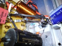
The other thing that comes to mind is the oscillation that the others have suggested. How's your bypassing and layout?
The other thing that comes to mind is the oscillation that the others have suggested. How's your bypassing and layout?
I changed gain to 3. Zobel filter is present (10R with 100nF).
Voltage measurements:
output - 25.3V
inverting input - 8.8V
non-inverting input - 19V
Voltage measurements:
output - 25.3V
inverting input - 8.8V
non-inverting input - 19V
Possibly a bad chip? The offset is enough to be a short internally. Your schematic doesn't show any problem that's readily apparent.
The other thing that comes to mind is the oscillation that the others have suggested. How's your bypassing and layout?
I already tried replacing chip and it does the same.
Attachments
Those readings taken at face value suggest a duff IC as FoMoCo hints at unless there is something really weird going on or incorrect pinouts in construction......
The inputs should be drawing essentially zero current and their obviously not with those readings.
The inputs should be drawing essentially zero current and their obviously not with those readings.
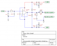
It is a new project. I want to drive unity gain power opamp with tube preamp.
But it is weird that I have two bad ICs :-(.
I should make proper PCB for it.
But it is weird that I have two bad ICs :-(.
I should make proper PCB for it.
Fakes maybe ? I don't know tbh.
Without a scope its impossible to know what is going on for sure.
A thought. If adding caps at various points in the circuit doesn't change the DC conditions at all then its pretty safe to say its not oscillating and the chip is faulty. If adding or changing cap values changes the DC levels then it could well be oscillating.
Open inputs? If one of the inputs at the IC is floating, it could latch at either supply rail. And the input pins may very well still read very close to 0V.
Measure voltage to ground from + and - IN pins.
Also with power off measure continuity from -IN to OUT pin.
If it's open, even a feeble offset (biasing current through the input resistor) may slam it against a rail.
Measure straight at the IC legs, don't trust the PCB or Protoboard.
Also with power off measure continuity from -IN to OUT pin.
If it's open, even a feeble offset (biasing current through the input resistor) may slam it against a rail.
Measure straight at the IC legs, don't trust the PCB or Protoboard.
Something is wrong with your non-inverting input it sounds like. Even with 47k input resistor, it should not be at such a high voltage sitting static. It should be at like 7mV or so. Also, that part IS unity gain stable, according to the gain/phase plot. Check the voltages on all your pins.. Make sure the supply voltages are good, make sure the inverting and non-inverting voltages are the same (if they aren't the op-amp is no longer in regulation and something is wrong). This is the main problem you are having now.
The Opamp WANTS its input voltages to be same. If the non-inverting (+) input is higher than the inverting (-), it will swing the output higher to make them match. Now look at your voltages, your inverting input is high, so it has swung the output as far as it can trying to match them. This is an over-simplified view of a VFB opamp, but it helps understand whats going on some.
The Opamp WANTS its input voltages to be same. If the non-inverting (+) input is higher than the inverting (-), it will swing the output higher to make them match. Now look at your voltages, your inverting input is high, so it has swung the output as far as it can trying to match them. This is an over-simplified view of a VFB opamp, but it helps understand whats going on some.
- Status
- Not open for further replies.
- Home
- Amplifiers
- Chip Amps
- OPA548 unity gain