I agree, with your scope readings (notice those notches - current limiting I think).
I was refering to supply voltages - not output voltages.
I think we agree on the results.
Shoog
I was refering to supply voltages - not output voltages.
I think we agree on the results.
Shoog
The statement should be clear: stay far enough away from 2A and it behaves as it should. Its clearly not the right OpAmps for lots of power in low impedance.
If you want to build chipamps, i suggest OPA549 instead of this one. I have only good experience with it. Also i don´t use any chipamp for music, i just built them for fun, and will use the OPAs for power supplys or so...
I have no experience with nationals chips, because they don´t like me so much as TI and don´t want to give me samples.
I like the Zens much more, i have V2, V4, and Zen lite running.
I have no experience with nationals chips, because they don´t like me so much as TI and don´t want to give me samples.
I like the Zens much more, i have V2, V4, and Zen lite running.
Try putting a bunch on speakers in series to achieve a higher impedance and then you could give that chip a go and see how it performs. Alternatively if you own a scope just try probing it while running it into a resistance of a higher resistance (play with the value). I'm curious to see how it measures with higher impedances, I might even do it myself if I feel inclined.
My point would be that for the average Jo, with the average setup this chip just will not fly. The National chips are designed specifically for this job and seem to do a very good job of it, why make life difficult for yourself by trying to get a square peg into a round hole.
I too have difficulty getting samples from National and unfortunately I don't have a big enough order to get them from Farnell at the moment- so I am a bit stuck.
Shoog
I too have difficulty getting samples from National and unfortunately I don't have a big enough order to get them from Farnell at the moment- so I am a bit stuck.
Shoog
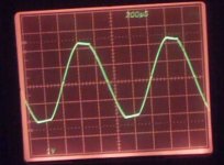
till said:supply +- 25V
sine wave 1kHz in,
2,83V output in 10Ohm
excuse bad camera quality:
The notches you see are the classical xover distortion, meaning the bias is too low. But anyway, if you see this sine wave when driving your speaker, it is not distorting a lot, and unless you are trained in recognizing THD, this should sound perfectly OK.
Again, try to scope with the speaker connected, try a couple of frequencies, if they look reeasonably OK, than it might be something with the preamp or whatever. You use a coupling cap, and the 1MOhm to ground as in the app note?
Jan Didden
I don´t know the circuit Shoog used.
I build a circuit for measurement flying wired, without input cap, but with a bipolar cap between amp and speakers (no so good idea to blow some 1000€ speakers ...) No 1MOhm.
Inverting, input 10 K, feedback 180K.
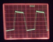
The main pupose of the scope measuremt for me was to prove the high THD at 16V + is the amp is clipping.
I think less than 1% THD is not much, measured acoustically, not with a power resistor as load and elektrically. How much THD is from the speaker?
I build a circuit for measurement flying wired, without input cap, but with a bipolar cap between amp and speakers (no so good idea to blow some 1000€ speakers ...) No 1MOhm.
Inverting, input 10 K, feedback 180K.
The main pupose of the scope measuremt for me was to prove the high THD at 16V + is the amp is clipping.
I think less than 1% THD is not much, measured acoustically, not with a power resistor as load and elektrically. How much THD is from the speaker?
Yes Till, this is about worst case (20kHz), and apparently you have some noise and/or hum. But even so this should not "distort as hell".
Shoog, I see no reason to blame it on the chip. You really should solve this, because with another chip you may have the same problem. Do you have a scope?
Jan Didden
Shoog, I see no reason to blame it on the chip. You really should solve this, because with another chip you may have the same problem. Do you have a scope?
Jan Didden
I have scoped it and seen distortion. It looks like current limiting distortion, with voltage been dumped to ground. The crossover distortion is not too significant.
I never used a 1Mohm resistor to ground, but this it not specified on the basic datasheet circuit.
The distortion I am hearing is not associated with the visable distortion that is been seen on the scope. It sounds like speaker breakup distortion in the midrange. The sound is relatively good at higher frequencies and very good at lower frequencies. this is not my speaker as it manifests on various fullrange drivers.
I have tried it with a passive preamp and with a Bride of Zen.
Until someone actually puts music through this chip and confirms whether they are getting any audible distortion there is not much more to add.
I would be more than relieved to hear that someone is putting a music signal into the chip and is getting a result that they are happy with. Once they have done this I will follow there advise as to how to get this to work for me.
Shoog
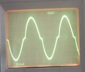
I´m playing musik (mono) with the OPA544 at the moment. I use some normal efficient speakers, small 2 way boxes, not the horn system. I can´t report much special audible distortion at normal volume level. It doesn´t sound like the Zen with the horns, but like musik. I scoped some sine wave at the output and with the ECM8000 in front of a connected speaker same time, the crossover distortion is visible at the output, but not out of the speaker. If you have current limiting distortion, your load is to low Z or you suck to much power out of the amp.
Shoog said:I have scoped it and seen distortion. It looks like current limiting distortion, with voltage been dumped to ground. [snip]Shoog
I have no idea what you are talking about. How does the waveform look? Can you make a drawing, scan that and post it? Indicate the voltage levels, time axis and the load resistor. How about posting the schematic (your schematic as you have built it. Draw it from the amp, not from the data sheet). We are all groping in the dark as to what your amp looks like, what the distortions is etc. I for one am willing to help you solve it, but a minimum effort from your part is required also.
Jan Didden
I will draw up a circuit for posting, but I don't believe it will enlighten enyone as it all standard opamp stuff as per the spec.
However let me quote from Hitware on the diyampchip forum who says;
"What I'm saying is that this chip (544) has gross crossover distortion. Even though the poop sheet says suitable for audio, it is not. (hi-fi audio anyways). "
It is part of all of the OPA power opamps to have current limiting. This manifests as high voltage spikes on the output waveform which are hidden because diodes dump the voltage to ground. It is only visable on the scope as small notches on the waveform, but the audio signiture is still there.I refer you to the following article;
http://sound.westhost.com/vi.htm
Shoog
Shoog said:I will draw up a circuit for posting, but I don't believe it will enlighten enyone as it all standard opamp stuff as per the spec.
However let me quote from Hitware on the diyampchip forum who says;
"What I'm saying is that this chip (544) has gross crossover distortion. Even though the poop sheet says suitable for audio, it is not. (hi-fi audio anyways). "
It is part of all of the OPA power opamps to have current limiting. This manifests as high voltage spikes on the output waveform which are hidden because diodes dump the voltage to ground. It is only visable on the scope as small notches on the waveform, but the audio signiture is still there.I refer you to the following article;
http://sound.westhost.com/vi.htm
Shoog
Shoog,
A couple of points. The figure with the voltage spikes in your referenced site is misleading. The mechanism described is correct, but any reasonable amp has a very small output impedance. That will take care of the spike energy, you will not see it on the output line. ANY amplifier has to cope with it, but it should be noted that this is only as big a problem as it looks with really very complex xover circuits & speakers.
I don't buy the current limit story; why should there be current limiting in normal use (as you do I understand). There is xover distortion, we have seen that, but unless your ears are asa sensitive as a cat's, it'll not sound "distorted as hell". (Still don't know how that sounds, any description?).
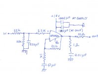
On your drawing (sure this is the amp as built, right? you didn't copy it from the data sheet?): doesn't show a supply cap at -18V. This may cause oscillation. Does show a 10 Ohm output resistor. That needs to go, of course. (Unless this is meant as the load, and you mean to ground the right side that says "output").
At the input you attenuate the input signal by 3. This may or may not be intentiaonally.
Again, when it distorts, what is the outp[ut level, load resistance, frequency? Or does it distort with music only? Is the distortion depending on the level?
Jan Didden
Maybe the 10 ohms on the output should be bypassed with an inductor, as a classical output filter?
Rune
Rune
The negitive supply line is filtered as per the positive supply line (omitted on drawing because of space). The input is through a 3uf cap before the voltage divider. The 10ohm resistor was the only way to tame the "distortion from hell" to a listenable level.
This chip does distort, I am not certain exactly what form that distortion takes.
The chip has an input sensativity of 0.7V so a 1/3 divider is correct. My circuit is not the problem because it is as per the datasheet.
I have ran out of patience trying to get some useful input on this thread and will revert to the LM1875, which I am confident will not distort in the same way.
I started this thread as a warning to other people not to launch into using a chip which "I consider from experience" to be unsuitable for the job. I believe that scope readings and specs are not presenting the whole story.
I ask the question, of all of the thousands of Gainclone builders I seem to be the only one who has experimented with this chip- and no-one else is recommending it. Draw your own conclusions.
Shoog
- Home
- Amplifiers
- Chip Amps
- opa544 will not work as a Gainclone.