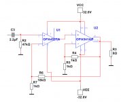
The OPA541 is a powerful chip.
Package is 11-pin TO-220.
When used with only a few parts it can output 9-10A and dissipate 125 Watt.
Power supply can be up to +/- 40 Volt.
The THD is low but not the best.
To perform with lower THD we can use a driver chip.
This will control the OPA541.
We need an op amp with max power supply +/- 40 Volt.
This is where OPA452 comes in.
Package is 7-pin TO-220 or DDPAK/TO-263.
OPA452 is unity gain stable.
The power supply is 2x24VAC.
I recommend one 300VA transformer.
Result is 48 Watt output in 8 Ohm.
With very low distortion.
Attachments
Have you built this? When I tried something similar there were stability issues. It's not as simple as this because the two opamps have very different bandwith and slew rate.
...use a driver chip.....We need an op amp with max power supply +/- 40 Volt......
Since U2 is run with gain of 2, U1 can be run with half the supply voltage, or +/-16V for your example. If U2 is rigged for gain of 3, U1 may never need a lot more than +/-13V, so "any" +/-18V-rated chip may do.
Last edited:
I think he chose the OPA452 not because of voltage but because its slew rate and bandwidth are on paper a close match for the OPA541. You cannot use "any" chip to drive the OPA541 because you will run into problems with stability as it is relatively slow compared to most normal op-amps. Look how complex TomCHR had to get to include an LM3886 inside a normal op-amp's feedback.
Just want to say that I enjoy your "ideas" from the drawing board and simulations very much, lineup.
In fact I bookmarked a couple projects that I would have started, had I not digged into too many projects.
Will you try this one for yourself or are just happy simulating and musing away?
Let me know if you need opa541, still have some samples here that I'd contribute.
Cheers and keep up the good work
Would a simple low pass on the driver work sufficiently to reduce bandwidth or would it still be prone to instability?I think he chose the OPA452 not because of voltage but because its slew rate and bandwidth are on paper a close match for the OPA541. You cannot use "any" chip to drive the OPA541 because you will run into problems with stability as it is relatively slow compared to most normal op-amps. Look how complex TomCHR had to get to include an LM3886 inside a normal op-amp's feedback.
"Look how complex TomChr....."
Look where?
That's Tom Christiansen, aka Neurochrome. Here's a link to a page on his website dealing with "stability" Taming the LM3886 Chip Amplifier: Stability – Neurochrome
There is no any composite circuit that Richie is referring to, which should be Modulus 86, and no any circuit of it I have seen.
By the way, any opamp can be slowed down to bear the dominant pole, a capacitor from output to minus input will do.
By the way, any opamp can be slowed down to bear the dominant pole, a capacitor from output to minus input will do.
Last edited:
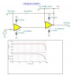
I did simulate your circuit, it looks very good. 0.0005%THD at 42w 1khz.
The spice models of both circuits have implemented distortion characters , I verified both.
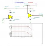
With 500 ohms feedback instead of 1k, it is more stable and lower distortion.
The spice models of both circuits have implemented distortion characters , I verified both.
With 500 ohms feedback instead of 1k, it is more stable and lower distortion.
Attachments
Last edited:
There is no any composite circuit that Richie is referring to, which should be Modulus 86, and no any circuit of it I have seen.
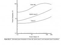
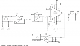
Do you have a copy of "Designing Audio Power Amplifiers" by Bob Cordell. Figure 31.3
I thought I had seen a schematic for modulus86, thought it was on Neurochrome website but you are correct it's not there now. For a start look up the Practical Electronics Texan amplifier.
I thought I had seen a schematic for modulus86, thought it was on Neurochrome website but you are correct it's not there now.
I remember. There was a network between the output of the op amp and the input of the 3886.
There's other ways to achieve stability criteria. https://www.ti.com/lit/ds/symlink/b...63898&ref_url=https%3A%2F%2Fwww.mouser.com%2F Look at figure 24. I've seen where there was a third resistor; the capacitor connects in the middle of the feedback resistor between output and inverting input.
Walt Jung details feedforward compensation in his IC Op Amp Cookbook. I've wondered if this could address stability issues with composite amplifiers. I've never investigated it. I think it would work.
This is the same issue faced with traditional discrete power amplifiers. The output devices are almost always the slowest devices in the circuit. Cdom is the traditional way to address this. All it does is slow down the front end of the circuit and provide a dominant pole, instead of having stacked poles at frequencies where the circuit still has loop gain.
Actually it wasn't the Texan amp, hazy memory. It was an old article in Practical Electronics or Practical Wireless about composite amps featuring LM1875 being driven by whatever opamp was "good" at the time. It may have been an article by Walt Jung.
FauxFrench tried it out applying meticulously to the instructions, the circuit doesn't work. The quiescent operating point cannot find, oscillating from rail to rail. It is the same result on simulator.
Last edited:
FauxFrench tried it out applying meticulously to the instructions, the circuit doesn't work. The quiescent operating point cannot find, oscillating from rail to rail. It is the same result on simulator.
are you referring to the figure I presented -- in fact Bob brought the amplifier to the NJ Audio Society a few years ago and we auditioned. It sounded wonderful
Bob's circuit is not a composite Bob Cordell's Super Gain Clone PCB (LM3886) and a stripped-down version: Compact3886,
The tested composite from the 70's article is here
https://www.diyaudio.com/forums/chi...ation-composite-amplifier-14.html#post6021102
The tested composite from the 70's article is here
https://www.diyaudio.com/forums/chi...ation-composite-amplifier-14.html#post6021102
a lot of effort is done by FF. He did this to avoid mixing with the LM1875 prallel thread
Chip-amps suited as power stage in a composite amplifier, LM1875/TDA2050 excluded.
Chip-amps suited as power stage in a composite amplifier, LM1875/TDA2050 excluded.
- Home
- Amplifiers
- Chip Amps
- OPA541 improved with OPA452