The MT3608 switches at 1.2MHz - it’s quiet at audio frequencies. The frequency is so high that the little choke and cap filter it very effectively.
The FFT of the 3608 can be seen in my thread on the Pocket Class A.
Apologies, good man for not being more clear in my post #280. I was referring to the Adafruit Switching Split Power Supply (±12V 500mA AC-DC Wall Wart) in my first diagram titled "Power Supply Plan A" in post #277.
I first introduced/proposed this switching split power supply in post #260 and subsequently it was brought up again by agdr and discussed in posts: #272; #273; and #274.
agdr mentioned that this particular power supply may be very noisy and without the switching frequency it is hard to know where it may fall... could be right in the audio range.
Completely understood on the MT3608 and trust that it is super quiet as you have stated however, I am shying away from that option your proposed due to the more advanced required electrical know-how to set it up, as well as the need for two(2) separate wall warts.
I am now leaning towards a single USB cable (from my PC or powered hub) feeding a RECOM Dual Isolated DC-DC Converter as proposed by agdr and shown in Power Supply Plan B in post #280).
Last edited:
You might take a look at these converters. I am using them for one of my projects - very nice and compact. Need 12v or input but that’s easy to find as a wall wart Class 2 (quietest option).
Traco Power
495-THN15-2425WIR
+/-24v out 315mA, 9v-36v input. Isolated rail. I use regulators after to dropnto +/-18v.
Traco Power
495-THN15-2425WIR
+/-24v out 315mA, 9v-36v input. Isolated rail. I use regulators after to dropnto +/-18v.
You might take a look at these converters. I am using them for one of my projects - very nice and compact. Need 12v or input but that’s easy to find as a wall wart Class 2 (quietest option).
Traco Power
495-THN15-2425WIR
+/-24v out 315mA, 9v-36v input. Isolated rail. I use regulators after to dropnto +/-18v.
Very interesting. They look very robust and well made. Do you happen to have a pic or link that shows how you set up from wall wart to PCB, especially showing how to wire into the Traco on a perf board and with those regulators?
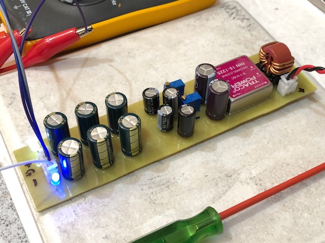
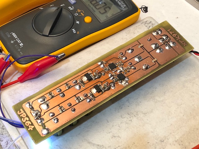
It’s the PSU for the Simple DC coupled HPA. I tested on home etched PCB. I used board mounted 4uV rms TPS7Axxxx regulators (QPFN) but final diy design uses TO220 7818/7918 regs with option for TO220 format TPS7A from LDOVR.com.
Simple High Performance DC Coupled Class A HPA with sub PPM THD
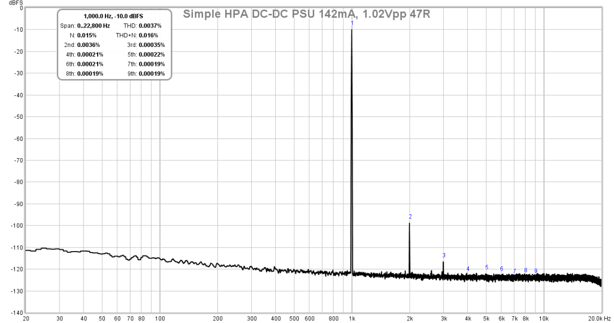
Here is the FFT for a wall mains PSU. It’s quieter than a battery:
Simple High Performance DC Coupled Class A HPA with sub PPM THD
Here is the FFT for a wall mains PSU. It’s quieter than a battery:
Last edited:
What an absolutely incredible build there my friend especially the home-brewed circuit board. Beyond impressed. My hat is off to you.It’s the PSU for the Simple DC coupled HPA. I tested on home etched PCB. I used board mounted 4uV rms TPS7Axxxx regulators (QPFN) but final diy design uses TO220 7818/7918 regs with option for TO220 format TPS7A from LDOVR.com.

However, that is WAY BEYOND my electronics knowledge and hand skill levels... in more than one manner too!
Last edited:
Thanks, the circuit is available in the GB as preamp board. I may have one left of the whole project. The hand etching and soldering are a little difficult I agree - which is why the production board skipped the TPS7Axxxx SMD parts in favor of through hole 7818 and 7918 TO220 parts. It’s a superb PSU though if you require a dual rail +/-18v supply for a power opamp. The OPA1688 handles up to +/-18v.
Where?Thanks, the circuit is available in the GB as preamp board.
Where?
Simple High Performance DC Coupled Class A HPA with sub PPM THD
It's the central long rectangular break-away board in the middle:
I like those PCB Mounts and Screws you are using in that case. Adhesive mounts correct?
I like those PCB Mounts and Screws you are using in that case. Adhesive mounts correct?
You mean the screws that go through the transistors with a blue/grey pad underneath?
No, those are 4-40 hexcap screws into drilled and tapped holes on the bottom panel of the case. The pads are thermally conductive silicone insulator sheets (vs greased mica of the old days). Drilling and tapping 2mm thick Aluminum is quick and easy.
So, I am preparing to order the remaining parts for this desktop build from Mouser and/or DigiKey. Would someone please kindly confirm if these are the correct 499R Load Resistors:
499R Load Resistor
And if I am not mistaken, I will need to install four (4) as follows:
499R Load Resistor
And if I am not mistaken, I will need to install four (4) as follows:
An externally hosted image should be here but it was not working when we last tested it.
Great question... unfortunately, I am barely treading water with this myself and have very limited knowledge. Here is the original post from agdr proposing the RECOM Converter (post #170) and the subsequent chatter regarding such (posts #171; #172; #277; #279; and #280). I don't see agdr mentioning anything about the need for EMI filtering.Do RECOM give recommendation about EMI filtering?
Would add some capacitors at output according datasheet.
JP
Last edited:
So, I am preparing to order the remaining parts for this desktop build from Mouser and/or DigiKey. Would someone please kindly confirm if these are the correct 499R Load Resistors:
Mmmm there is something wrong with your diagram of the Recom converter in post 292. There are no pins 12 & 13. Turns out you actually did have the correct diagram in your post 277 above, I led you astray on that one. I forgot about the common terminals on this model. On the Mouser product page here:
RW-0509D RECOM Power | Mouser
click on the "Datasheet" link. Then on the sheet scroll down and they have a diagram with the pinout. It says RW-1205D, but that is OK, all the converters in the chart have this same pinout.
So what you do:
- pins 22 & 23 (positive input to the 2 converter sections) connect together and go to the red/+ lead of your USB. You essentially have this correct in your diagram, except you don't explicitly show 22 & 23 being connected together.
- pins 2 & 3 (negative input to the 2 converter sections) connect together and go to the black/- lead of your USB. You essentially have this correct in your diagram, except you don't explicitly show 2 & 3 being connected together.
- You have pin 14, the positive converter output, correct on your diagram. Goes to the positive connection for battery 1 on the CMOY board.
- You have pin 11, the negative converter output, correct on your diagram. Goes to the negative connection for battery 2 on the CMOY board.
- To understand the final, common, (ground) connection between the batteries and the converter, please take a look at the CMOY schematic diagram at the project materials here:
This is for V1.2 of the dual CMOY, but the battery connection part is the same for all. Now take a look (zoom in on that area of the .png diagram with your mouse wheel) at the battery connections on the schematic diagram. You will see that Battery 1 positive feeds diode D1. That is the converter pin 14 connection we've mentioned above. Then see how Battery 2 negative goes to diode D2. That is converter pin 11 we've mentioned above.
BTW, those two diodes are simply polarity protection diodes. If the battery leads are accidentally connected backwards (or someone touches the 9V battery snaps to the 9V battery terminals backwards, easy to do) the diodes block and protect the rest of the circuit from the wrong polarity.
Now take a look at the remaining two battery terminals on the diagram, the negative (-) of battery 1 and the positive (+) of battery 2. They connect together on the CMOY PC board traces. That is your (real) ground! And real ground on the converter are the "common" pins, 9 & 16. Those two pins should be internally connected inside the converter to form a real ground, same as on the CMOY PC board.
So to wire, connect from the negative of battery 1 on the CMOY to either converter pin 9 or 16. Doesn't matter which, they are internally connected. Then connect from the positive of battery 2 on the CMOY to the remaining converter pin, 9 or 16, whichever is left. Note that since 9 & 16 are connected together in the converter, and since these two battery terminals are connected together on the CMOY pc board, you probably could use just one wire. But.. don't ") I learned a long time ago it is best to be thorough about things like this, not know the details inside the converter. 9 & 16 might not be connected together yet. Use the two wires and the CMOY PC board will connect them.
I learned a long time ago it is best to be thorough about things like this, not know the details inside the converter. 9 & 16 might not be connected together yet. Use the two wires and the CMOY PC board will connect them.
There are no pins 12 & 13 on the converter, like we've mentioned above, so those go away. I learned a long time ago it is best to be thorough about things like this, not know the details inside the converter. 9 & 16 might not be connected together yet. Use the two wires and the CMOY PC board will connect them.
And that is it!
No EMI filtering should be needed on the converter since the switching frequency is well above the audio range. But you guys are right, some converters do need that and the datasheet would show.
The 499 load resistors are fine. 9Vdc^2/499R = 0.16W, more than 1/8W (around 1/6W), these should be 1/4W or higher rated resistors.
Also, FWIW, I've ordered a few of those adafruit +/-12Vdc wall warts. When they get here I'll measure and see how clean the output is. Those could be quite handy in projects!
Last edited:
Many thanks for the detailed explanation; it was quite informative.Mmmm there is something wrong with your diagram of the Recom converter in post 292. There are no pins 12 & 13. Turns out you actually did have the correct diagram in your post 277 above, I led you astray on that one. I forgot about the common terminals on this model. On the Mouser product page here:
RW-0509D RECOM Power | Mouser
click on the "Datasheet" link. Then on the sheet scroll down and they have a diagram with the pinout. It says RW-1205D, but that is OK, all the converters in the chart have this same pinout.
So what you do:
- pins 22 & 23 (positive input to the 2 converter sections) connect together and go to the red/+ lead of your USB. You essentially have this correct in your diagram, except you don't explicitly show 22 & 23 being connected together.
- pins 2 & 3 (negative input to the 2 converter sections) connect together and go to the black/- lead of your USB. You essentially have this correct in your diagram, except you don't explicitly show 2 & 3 being connected together.
- You have pin 14, the positive converter output, correct on your diagram. Goes to the positive connection for battery 1 on the CMOY board.
- You have pin 11, the negative converter output, correct on your diagram. Goes to the negative connection for battery 2 on the CMOY board.
- To understand the final, common, (ground) connection between the batteries and the converter, please take a look at the CMOY schematic diagram at the project materials here:
This is for V1.2 of the dual CMOY, but the battery connection part is the same for all. Now take a look (zoom in on that area of the .png diagram with your mouse wheel) at the battery connections on the schematic diagram. You will see that Battery 1 positive feeds diode D1. That is the converter pin 14 connection we've mentioned above. Then see how Battery 2 negative goes to diode D2. That is converter pin 11 we've mentioned above.BTW, those two diodes are simply polarity protection diodes. If the battery leads are accidentally connected backwards (or someone touches the 9V battery snaps to the 9V battery terminals backwards, easy to do) the diodes block and protect the rest of the circuit from the wrong polarity.Now take a look at the remaining two battery terminals on the diagram, the negative (-) of battery 1 and the positive (+) of battery 2. They connect together on the CMOY PC board traces. That is your (real) ground! And real ground on the converter are the "common" pins, 9 & 16. Those two pins should be internally connected inside the converter to form a real ground, same as on the CMOY PC board.So to wire, connect from the negative of battery 1 on the CMOY to either converter pin 9 or 16. Doesn't matter which, they are internally connected. Then connect from the positive of battery 2 on the CMOY to the remaining converter pin, 9 or 16, whichever is left. Note that since 9 & 16 are connected together in the converter, and since these two battery terminals are connected together on the CMOY pc board, you probably could use just one wire. But.. don'tThere are no pins 12 & 13 on the converter, like we've mentioned above, so those go away.
And that is it!
No EMI filtering should be needed on the converter since the switching frequency is well above the audio range. But you guys are right, some converters do need that and the datasheet would show.
The 499 load resistors are fine. 9Vdc^2/499R = 0.16W, more than 1/8W (around 1/6W), these should be 1/4W or higher rated resistors.
Also, FWIW, I've ordered a few of those adafruit +/-12Vdc wall warts. When they get here I'll measure and see how clean the output is. Those could be quite handy in projects!
Patiently await your findings/thoughts on the Adafruit Switching Split Vdc Wall Warts.
POWER SUPPLY PLAN B - FINAL VERSION
RECOM POWER RW-0509D ISOLATED DC-DC CONVERTER 4.5V to 9V via USB 2.0 CABLE SET-UP DIAGRAM
An externally hosted image should be here but it was not working when we last tested it.
Would the best way to connect the input pins 22 with 23 together (as well as, 2 with 3) on the perf board be via a solder bridge, correct?
Regarding the soldering of the two 499R resistors... should they be soldered first, close to the perf board, between 11 & 9 and 14 & 16 then the wires soldered after that or vice versa?
Many thanks for the detailed explanation; it was quite informative.
Your connection diagram is correct now!
To short 22,23 together (and 2,3) what I usually do on perfboards is just bend one pin over until it touches the other (if the pin is that long), bend it one turn around the other lead (for mechanical stability) and solder. Trim the excess.
Alternatively take a new piece of wire, wrap one turn around each lead, and solder to both leads. Trim the excess. Clipped-off excess resistor leads are good for this kind of thing. I usually have a few sitting on the table waiting to go to the trash.
I would solder the resistors first, like you have described.
Thank you offering that alternative wiring option using excess resistor leads as the RECOM converter pins are only 3.81mm in length and after being passed through the perf board there will only be slightly over 2mm remaining.Your connection diagram is correct now!
To short 22,23 together (and 2,3) what I usually do on perfboards is just bend one pin over until it touches the other (if the pin is that long), bend it one turn around the other lead (for mechanical stability) and solder. Trim the excess.
Alternatively take a new piece of wire, wrap one turn around each lead, and solder to both leads. Trim the excess. Clipped-off excess resistor leads are good for this kind of thing. I usually have a few sitting on the table waiting to go to the trash.
I would solder the resistors first, like you have described.
After placing the converter on the perf board (pins through the holes) I will slightly solder the pins to keep the converter firmly in place. I plan to twist the 499R resistor leads around each converter pin (e.g. 9 with 11 and 14 with 16). I then will push these resistor leads down flush to the board before soldering them (leaving room on the converter pins for the output to battery wiring). Finally, clipping off any/all excess resistor lead.
For the output to battery wiring leads I will twist and solder them to the remaining (exposed) converter pin ends. Would it be wise to encase each of these soldered points (converter pin-resistor-output to battery wiring points) with a small spot of black hot glue to protect them?
Are there any grounding and/or shielding precautions one should take in regards to this amp design especially if using an entirely non-metallic case?
Would covering the entire inside of the case with adhesive copper foil taping be worthwhile?
HI
Your soldering plans in post 298 sound fine. I didn't know the converter leads were that short! The glue wouldn't be necessary unless you feel it is needed for mechanical stability, or to insulate the soldered joints from something touching them.
Good that you mentioned twisting the wire pair going from each Super CMOY board battery +/- to the converter pins. Extremely important.
Shielding the inside of your non-metallic case can't hurt! But headphone amps typically have very low voltage gain. Much less likely to pick up EMI than a microphone pre-amp. However if you have an electrically noisy environment - cell phone towers, etc - then shielding may be necessary.
Yet another good thing about the OPA1688 is FET inputs. The diode junctions on bipolar input op-amps are what tends to de-modulate incoming EMI, turning the thing into a radio receiver.
Last edited:
- Home
- Amplifiers
- Headphone Systems
- OPA1688 Super CMOY, 2x 9V with real ground and headphone relay - PCBs