Or a hair dryer's big brother, a heat gun for heatshrink tubing. I have this inexpensive model which goes up to 1500 Watts

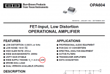
As others have said, the absolute maximum rating of the OPA1656 is 40V between the supplies, recommended is up to 18V. I can't give a blanket statement for all the OPA16xx op amps, because they're not all on the same process technology. I also have to question the logic behind running the absolute highest supply voltages you can if you're not running into dynamic range issues. You're just increasing the power dissipating in the op amp (i.e. making it run hotter) without really benefitting performance. If you look at Figure 6-31 of the OPA1656 datasheet you'll notice that above about 6V the supply current no longer increases with supply voltage, hence the internal transistors are running at the same current densities and the amplifier transfer function isn't changing. This wasn't true on older op amps, and these old habits seem to die hard in analog design.
Specsmanship drives board designers to maximize "phono overload margin" for bragging/marketing purposes. To get 30dB overload margin with 5mV RMS nominal input and 40dB gain @ 1 kHz { incl RIAA eq } requires 15.8V RMS at the output. Which in turn needs plus and minus 23 volt power supplies.
Oh I'm well aware the the specmanship justifications, especially for phono pre amps. I just felt in a DIY environment it was safe to question the status quo 🙂 All that wonderful overload margin gets thrown away when the customer has to plug their phono preamp into a piece of equipment that can't handle a 15.8V RMS input signal without clipping.Specsmanship drives board designers to maximize "phono overload margin" for bragging/marketing purposes. To get 30dB overload margin with 5mV RMS nominal input and 40dB gain @ 1 kHz { incl RIAA eq } requires 15.8V RMS at the output. Which in turn needs plus and minus 23 volt power supplies.
I suspect the main problem is overload recovery, in the presence of static discharge, scratches, and warps. Which needs enough headroom to get around any problems associated with overload recovery.Specsmanship drives board designers to maximize "phono overload margin" for bragging/marketing purposes. To get 30dB overload margin with 5mV RMS nominal input and 40dB gain @ 1 kHz { incl RIAA eq } requires 15.8V RMS at the output. Which in turn needs plus and minus 23 volt power supplies.
An attempt to get around this problem was tackled in the 1960's in the first Cambridge Audio product. The input stage was a two transistor "op amp" (it wasn't strictly that). That put the 47k input resistor in series with the input (with noise disadvantage of course), and the feedback incorporated the volume control. Thus the phono input stage was a flat, variable gain stage. That then fed the RIAA stage, Baxandall tone controls and switchable filters before the power amp.
The aim of the gain structure was that it was impossible to overload any stage prior to the power amp going into clipping.
Actually there is a good chance 15V RMS will not cause clipping. If the preamp input first goes to volume pot which is rarely set higher than -30dB for normal listening, the power amp still might avoid clipping.Oh I'm well aware the the specmanship justifications, especially for phono pre amps. I just felt in a DIY environment it was safe to question the status quo 🙂 All that wonderful overload margin gets thrown away when the customer has to plug their phono preamp into a piece of equipment that can't handle a 15.8V RMS input signal without clipping.
https://www.utmel.com/productdetail/texasinstruments-opa1656id-7871179 says 18 in stock, no price visible though.
https://www.win-source.net/texas-instruments-opa1656idr.html
Also indicates plenty stock. They're trustworthy, I have used them with good luck multiple times.
Also indicates plenty stock. They're trustworthy, I have used them with good luck multiple times.
I disagree. I bought chips from them that did not work as expected. I filed a tech support request to the manufacturer (Analog Devices). They were helpful in the beginning but closed the support request because win-source is not their trusted supplier.https://www.win-source.net/texas-instruments-opa1656idr.html
Also indicates plenty stock. They're trustworthy, I have used them with good luck multiple times.
Hi,
Question to Ti folks, please: are ther eany DIL8 or soic8 Bjt or Fets arrays on the market? I know there are in DIL14 but DIL8 ? Needs : avoiding sorting out of 3 legs transistors for discrete designs. I am tired by seing people doing discrete op275, and so on. So if thermal and noise issues are an issue I would like to know id there is a path with semi discrete design with tigtht idss parameters please ?
As for the 1655/56 discussion : what is qn acceptable distance between the voltages pins and the gnd for HF decoupling, please ?
More on topic, I am a little frustrated by the "as close as physically possible". What does that mean for audio ? Am I ok with a 2mm trace from the 0,1 uF cap with a 5mm spacing to ground or should I go with a 0405 smd with an hearing difference there ? I ask causd I do like this 1656 but I am strugling to find the corrzct values for decoupling.
Look at TI web site, but I know they do not make what you are asking for, know one does anymore because you are one of the very few making demands for such parts.
if you care to research and read, TI has many documents and test boards to use as examples of proper pcb layout
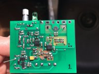
Look at a picture of Victors oscillator using a opa1656, it might help you answer your ?'s
How's my soldering 🙂 It even works now that I figured out how to tune it 🙂
Enjoy your search and research
if you care to research and read, TI has many documents and test boards to use as examples of proper pcb layout
Look at a picture of Victors oscillator using a opa1656, it might help you answer your ?'s
How's my soldering 🙂 It even works now that I figured out how to tune it 🙂
Enjoy your search and research
Attachments
Last edited:
Is OPA1656 suitable for composite amplifier with TDA7293?
Or LME49720 is a better solution in this case?
Or LME49720 is a better solution in this case?
Composite amplifiers are picky and always contain a lead/ lag network to match the characteristics of opamp and power IC. Both are very good opamps and I don't see why either of them wouldn't work, but most likely not in the exact same circuit.
Fyi, the TI online shop have the opa1656 in stock again, so I just bought a 1000 pcs reel.... I don't really understand why TI direct actually are cheaper than my local official distributor....
Last edited:
- Home
- Vendor's Bazaar
- OPA1656: High-Performance CMOS Audio Op Amp