In short, OPA1656 shows very high THD level when voltage below +-9 Volts.
Experimenting with Sallen-Key Filter, I observed unusually high distortion level with OPA1656, reported in this thread :
https://www.diyaudio.com/community/...range-oscillator.205304/page-490#post-7012005
and more here
https://www.diyaudio.com/community/...range-oscillator.205304/page-491#post-7014043
To simplify test set-up I change circuits to :

You don't have to use SA, distortion level obvious on oscilloscope screen.
I repeated measurements a few times, using sets of resistors:
1). 10 Ohm - 10 kOhm, 2). 100 Ohm - 100 kOhm, 3). 1 kOhm - 1 MOhm 4). 10 kOhm - 10 MOhm
Set 1 produces no visual deviation at all.
Sets 2-4 shows almost the same:


Disregard offset issue with +-3V power, see abnormality with +-6V. Blue line - Input 1Vp-p, yellow - output.
Experimenting with Sallen-Key Filter, I observed unusually high distortion level with OPA1656, reported in this thread :
https://www.diyaudio.com/community/...range-oscillator.205304/page-490#post-7012005
and more here
https://www.diyaudio.com/community/...range-oscillator.205304/page-491#post-7014043
To simplify test set-up I change circuits to :
You don't have to use SA, distortion level obvious on oscilloscope screen.
I repeated measurements a few times, using sets of resistors:
1). 10 Ohm - 10 kOhm, 2). 100 Ohm - 100 kOhm, 3). 1 kOhm - 1 MOhm 4). 10 kOhm - 10 MOhm
Set 1 produces no visual deviation at all.
Sets 2-4 shows almost the same:
Disregard offset issue with +-3V power, see abnormality with +-6V. Blue line - Input 1Vp-p, yellow - output.
Note that with Sallen & Key and other feedback based filters, the internal circuit node voltages can be much higher thanthe input and output levels. Often a source of distortion, especially with limited supply voltages.
BTW in your scope pics I don't see any distortion, only level differences.
In the first pic it is the scope that clips, you should move the yellow wave up on the screen.
Jan
BTW in your scope pics I don't see any distortion, only level differences.
In the first pic it is the scope that clips, you should move the yellow wave up on the screen.
Jan

I don't see any reason, why circuit node voltage in Sallen-Key filter would be any different for opa1652 /opa1688 and for opa1656. Especially with 33nF cap.
Same apply to THD measurements circuits, look again, distorted positive half-wave Only. Any other OPA in this circuits would stay as in picture 9V in the specified by DS voltage range. Gain must be exactly +1.
Same apply to THD measurements circuits, look again, distorted positive half-wave Only. Any other OPA in this circuits would stay as in picture 9V in the specified by DS voltage range. Gain must be exactly +1.
I didn't say it is different with different opamps.
Again, I see no distortion in any of your graphs. Which one are you referring to? The first one? That's just a bad scope setting.
Edit: I looked at the first link in your 1st post. All I see is a bunch of scope pictures all almost the same as the generator distortion. That means that the opamp basically has much, much less distortion, which cannot be deduced from these pics.
I think you are chasing a ghost.
Jan
Last edited:
You know how sine wave with offset differs from sine wave with gain not correct? Settings on the oscilloscope were not changed in between 3 pictures.@MagicianT , have you measured the DC offset??
I see a lot of confusion. Sallen-Key circuits is much more complex to analyze , my initial attempts to insert 2.4k into negative feedback that I mention in another thread is the first things that come to my mind. There are too many parameters involved, PS Voltage, R & C on both inputs, etc.
This is why I bring another circuits right from OPA1611 data sheet (and many many others)
First line in the table G=+1 , with resistors 1k & 1M would means distortion gain 1001, but input signal G stays +1.
I used this circuit always, 100-200 OPA different makers & types were evaluated for many years . My new SA based on MAX11270 could measure -130dB THD with 2 frame per seconds - real time. This is first ocasion I see an issue, so big in scale. It's visible on a scope!
Definitely a Bug, TI should not specify OPA from 4.5V - minimum 18V from my perspective.
Picture in the middle, 1k6V - move a mouse over it shows a bubble with a name.Can you tell me in which scope pic you see this distortion?
Or maybe show this pic?
Jan
No, it's not a DC offset, this is DC offset + Gain Error - huge error, about 10% off. Peak-to Peak value yellow & blue channels must be the same, if not - linearity & distortion problems. It could be shifted up and down depends on DC offset, but newer magnitude variation.
It is a DC offset. However it seems there is no use to debate with someone who is unwilling to learn and who even does not know how the harmonic distortion of the sine wave looks like. BTW, he has a scope and the scope definitely has an FFT measurement. No problem to measure harmonic distortion, then, if there is any.It looks like DC offset to me.
Right, it's not like a communist party assembly, no opinion expression is expected. Avoid "objection, your honour" stupidity.who even does not know how the harmonic distortion of the sine wave looks like. BTW, he has a scope and the scope definitely has an FFT measurement. No problem to measure harmonic distortion, then, if there is any.
Someone could just put a couple resistors into the breadboard, set TL082 and see what it looks like. Than put opa1656 into same board, and make a conclusion.
PS: Have you ever seen a FFT on oscilloscope screen? Crap. But I respect Rigol on any aspect, except FFT chart and noise level.
Going back to post #1 and the circuit you posted, are we just looking at performance limitations from running an opamp at very high noise gain while on low supplies?
I set this up years ago just for fun. I can also imagine you might see a DC shift using the opamp in an unsuitable circuit. Decent opamp vs jelly bean. In the real world with real parts you may well find odd effects.


I set this up years ago just for fun. I can also imagine you might see a DC shift using the opamp in an unsuitable circuit. Decent opamp vs jelly bean. In the real world with real parts you may well find odd effects.
You use the opamp in a 1000x gain config, so you can expect less than 1000x actual gain. You show input/output curves overlaid, so how did you get the output divided down to the input? Scope attenuator? Trying to get these small differences measured with an 8-bit cheap scope is, well, ambitious.Picture in the middle, 1k6V - move a mouse over it shows a bubble with a name.
No, it's not a DC offset, this is DC offset + Gain Error - huge error, about 10% off. Peak-to Peak value yellow & blue channels must be the same, if not - linearity & distortion problems. It could be shifted up and down depends on DC offset, but newer magnitude variation.
The same with trying to interprete tiny waveform differences between scope channels as 'distortion' of the opamp.
That opamp runs rings around that scope, even at 60dB.
From earlier postings, I expect you to be too stubborn to think seriously about it, but you're wasting your time this way and learn nothing.
Jan
A single stage gain of 1000 using resistors of megaohms is not what opamps are designed for. Limit each stage to 10 to 20x gain max if possible, use feedback resistors of lower value, a few 100k is about the max typically seen for solid-state audio circuitry. Many audio opamps have GBW of 10 to 20MHz or so, so at a gain of 1000 the bandwidth will have dropped to 10--20kHz - completely inadequate for audio.I repeated measurements a few times, using sets of resistors:
1). 10 Ohm - 10 kOhm, 2). 100 Ohm - 100 kOhm, 3). 1 kOhm - 1 MOhm 4). 10 kOhm - 10 MOhm
Also audio opamps may have enough input offset voltage to saturate the output for such high gains - if the input offset is +/-3mV and the gain is 1000, the output offset is +/-3V, or maybe much worse if a bipolar opamp with extra offset due to bias resistors.
Often the headline distortion figures in datasheets are for gains of +/-1 only.
Distortions less than 5% or so can be hard/impossible to see on a 'scope screen, the eye doesn't act as a spectrum analyzer.
Think I'd continue old thread, instead of starting new one. I build another hobby project, modified version of
"National Semiconductor
Application Note 24
M. Yamatake
April 1986"
A Simplified Test Set for
Op Amp Characterization.
In essence, idea is similar to shown in original post circuits, drive input CM of the OPA and using gain of the DUT itself measure RTI offset.
Read app note for details. My "upgrade" consists of removing integrator - replace to DAC (kind of software integrator) and track data by internal nucleo-G474 adc -> streaming to PC.
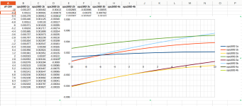
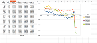
I 'd show two IC, opa1692 (good one) and opa1656. As you can see, opa1656 exibits sharp change in RTI offset about 6-7V (powered +-12.5V).
Data for opa1692 "noise removed" version.
Testing 20-30 OPA's I have in stock, different types and makers, didn't find any that have this gluk. Some have real problem with linearity, where changes in offset may reach 100's uVolt, I can post more results if interesting.
Strange that all aplication examples of opa1656 in DS have gain G >= 2.
"National Semiconductor
Application Note 24
M. Yamatake
April 1986"
A Simplified Test Set for
Op Amp Characterization.
In essence, idea is similar to shown in original post circuits, drive input CM of the OPA and using gain of the DUT itself measure RTI offset.
Read app note for details. My "upgrade" consists of removing integrator - replace to DAC (kind of software integrator) and track data by internal nucleo-G474 adc -> streaming to PC.
I 'd show two IC, opa1692 (good one) and opa1656. As you can see, opa1656 exibits sharp change in RTI offset about 6-7V (powered +-12.5V).
Data for opa1692 "noise removed" version.
Testing 20-30 OPA's I have in stock, different types and makers, didn't find any that have this gluk. Some have real problem with linearity, where changes in offset may reach 100's uVolt, I can post more results if interesting.
Strange that all aplication examples of opa1656 in DS have gain G >= 2.
Attachments

@MagicianT thanks for reporting on these interesting results, but what does RTI and DS stand for?
edit: I found direct link to the app note you mentioned:
LM709
Application Note 24 A Simplified Test Set for Op Amp Characterization
Literature Number: SNOA637
https://www.ti.com/lit/pdf/snoa637
edit: I found direct link to the app note you mentioned:
LM709
Application Note 24 A Simplified Test Set for Op Amp Characterization
Literature Number: SNOA637
https://www.ti.com/lit/pdf/snoa637
Last edited:
That mean Refer To Input and DataSheet.what does RTI and DS stand for?
Disregard offset issue with +-3V power, see abnormality with +-6V. Blue line - Input 1Vp-p, yellow - output.
I am checked with 3). 1 kOhm - 1 MOhm circuit (noise gain 1001) and could not confirm such symptoms.
In other words, I have varied the supply voltage from ±3V to ±15V, but the input and output are almost the same value.
Also, in your picture, the output offset seems to vary greatly with Vs=±3V: -450mV, ±6V: -76mV, and ±9V: -5mV, but the one I checked was almost constant and unchanged with respect to the power supply voltage variation.
Vs=±6V,
Top is input, bottom is output (Offset: approx. -305mV)
V: 200mV/div, H: 0.2msec/div
Is it possible that the input circuitry is damaged and deteriorating?
Have you verified that more than one unit exhibits similar symptoms?
I have checked with a total of 5 units, 2 OPA1656 and 1 OPA1655, and the output offsets are different for each, but otherwise similar.
Last edited:
Yes, source is legitimate - mouser. Tested 2 units, both channels, I have 2 more - not soldered yet to soic-DIP8 adapters.
I see confusion, regarding test setup and objective. I did testing with different power voltage 2 years ago seens the issue with abnormal THD level was not clear to me.
Now all obvious, it's not PSRR related, so power voltage doesn't need to be changed.
Input Common voltage test, simply:
1. apply power voltage to IC;
2. use circuits from initial message of this thread;
3. SLOWLY drive input from SG, or using potentiometer from V- to V+ ;
4. connect Voltmeter in between input and output of the OPA , that capable to register ~100 uV (having gain 1000 and jump in offset 2-6 uV expected abrupt voltmeter indication about 2-6 mV)
5. observe abnormality around 1/2 V+, in my case +6-7 vol'ts when powered +-12.5V
In other words, I have varied the supply voltage from ±3V to ±15V, but the input and output are almost the same value.
I see confusion, regarding test setup and objective. I did testing with different power voltage 2 years ago seens the issue with abnormal THD level was not clear to me.
Now all obvious, it's not PSRR related, so power voltage doesn't need to be changed.
Input Common voltage test, simply:
1. apply power voltage to IC;
2. use circuits from initial message of this thread;
3. SLOWLY drive input from SG, or using potentiometer from V- to V+ ;
4. connect Voltmeter in between input and output of the OPA , that capable to register ~100 uV (having gain 1000 and jump in offset 2-6 uV expected abrupt voltmeter indication about 2-6 mV)
5. observe abnormality around 1/2 V+, in my case +6-7 vol'ts when powered +-12.5V
- Home
- Source & Line
- Analog Line Level
- OPA1656 distortion when using at low voltage.