Hi,
I have to increase gain in this circuit by 12dB:
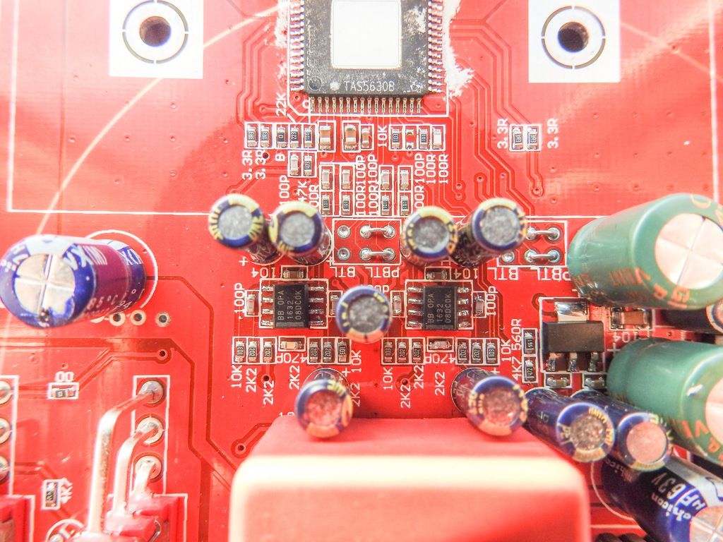
Anyone know how to do it?
Tried increasing 10k feedback resistors to 40k but this reduced gain and/or added roll off in freq response.
Thanks in advance for any info!
I have to increase gain in this circuit by 12dB:
Anyone know how to do it?
Tried increasing 10k feedback resistors to 40k but this reduced gain and/or added roll off in freq response.
Thanks in advance for any info!
Last edited:
We would need to see the circuit to make an informed decision. Sounds like the 10k isn't what you thought it perhaps was. The opamps could actually be configured as unity gain with all the resistors simply forming an active filter. That's not easy to change without hacking the board about.

if you short r63,r65,r69,andr71 you will have double the gain; but half of the input impendace; you will need to increase 10uF capacitors to a bigger value
Guess we all have different ideas on this. I would leave the input side of this alone and raise the four 10k feedback resistors to get the gain you need (say to 20k), with appropriate reduction of the two 150pf (82pf would be very close) caps.
well; it`s depend on what tools and parts you have; if you have a rework smd station and 0603 resistors is better to replace the 10k resistors; if you have just a letcon and your not familiar with smd soldering put some 22-47uF caps and short the 2.2k resistors
why would the 10k to 40k change reduce gain then and next if original 10k created 80khz low pass (given), how is it possible that 40k give instantly audible rolloff, so probably 10khz or lower low pass, I understand it drops (would guess to ~40khz) why so much more ?
why would the 10k to 40k change reduce gain then and next if original 10k created 80khz low pass (given), how is it possible that 40k give instantly audible rolloff, so probably 10khz or lower low pass, I understand it drops (would guess to ~40khz) why so much more ?
Quite possible that the resistors you changed were not the gain resistors. If you changed the resistors on the input side instead that would be compatible with reduced gain and reduced bandwidth.
These boards are a pain to figure out!
Jan
The OPA1632 datasheet recommends keeping Rf low. I would say 10k is already pretty high considering it recommends 400R/4k for a gain of 10.
well; it`s depend on what tools and parts you have; if you have a rework smd station and 0603 resistors is better to replace the 10k resistors; if you have just a letcon and your not familiar with smd soldering put some 22-47uF caps and short the 2.2k resistors
I have soldering station with narrow blower and it is not too much trouble to resolder anything.
The only problem is that I don't have any experience with opamp circuits.
Thanks to all for trying to help!
I could desolder "100p" capacitor and measure it with dm4070 meter that I have somewhere.
Edit: I measured it and meter says 34pF
Edit: I measured it and meter says 34pF
Last edited:
if you short r63,r65,r69,andr71 you will have double the gain; but half of the input impendace; you will need to increase 10uF capacitors to a bigger value
Doube meaning double the voltage or double gain factor?
If double the voltage than, unfortunately, it is not enouh.
I need at least to quadruple voltage to achieve even half of adverised power. When stock, I'm measuring 5w@4ohm, input via bluetooth, all maxed (phone and amp potentiometer) to maximum, and that is with 48v psu. Input via rca, same thing.
TI quote an input sensitivity of 1vrms.
Perhaps you would be better with a preamp in front of this, rather than hacking the board around.
Perhaps you would be better with a preamp in front of this, rather than hacking the board around.
Hi brighter,
That circuit looks like it has 12dB already in it, are you sure you need an additional 12dB? Might be useful to download ti filter pro and simulate a 1st order multiple feedback (MFB) fully differential circuit. Free from the TI website.
This process should only take a few minutes to download install and sim. Simply set the filter order to fixed 1 order. After that change the feedback resistors to 10k and the program automatically calculates the capacitance and gain resistor values. If you ignore the passive 1st pole input filter you should be close enough to the original filter response but with your desired increased gain.
- Status
- Not open for further replies.
- Home
- Amplifiers
- Class D
- Opa1632 gain in 5630evm circuit