Just starting to layout my headphone amplifier using the 4 x OPA1622, this project started from needing a headphone amplifier that could drive 4 x 32 ohm headphones from a digital source and needed or I wanted it to be battery powered ; my family enjoy watching movies together and headphones are our choice for listening and so this project came about.
The design will have individual volume control for each outlet and have 3 x sources of audio available, USB Audio Bridge, Optical SPDIF and stereo balanced analog inputs as well as balanced outputs all using mostly TI.com ICs. DIR9001 for digital interface, PCM1794A DAC, OPA1622, OPA1656 and OPA1637 for balanced output drive. Volume control can be selected for the XLR outputs or jumper out on the main PCB.
battery management is using TI.com BQ25616RTWR IC.

Hey man, how's it going? Any progress? Do you need any help from us? Please keep us updated!Just starting to layout my headphone amplifier using the 4 x OPA1622, this project started from needing a headphone amplifier that could drive 4 x 32 ohm headphones from a digital source and needed or I wanted it to be battery powered ; my family enjoy watching movies together and headphones are our choice for listening and so this project came about.
The design will have individual volume control for each outlet and have 3 x sources of audio available, USB Audio Bridge, Optical SPDIF and stereo balanced analog inputs as well as balanced outputs all using mostly TI.com ICs. DIR9001 for digital interface, PCM1794A DAC, OPA1622, OPA1656 and OPA1637 for balanced output drive. Volume control can be selected for the XLR outputs or jumper out on the main PCB.
battery management is using TI.com BQ25616RTWR IC.
View attachment 1086502
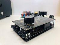
Well its been a while since I posted, but the DAC Headphone amplifier has evolved into this so far.
I still have the older more complex design, But I decided to knock out a more simpler design with a very powerful output stage.
The current configuration is a DIR9001 TOSLINK receiver with a PCM5102A DAC which drives an OPA1656 op-amp that drives two pairs of discrete power MOSFETs
I will be updating it with the CS8416 192khz receiver and addinga MCU control for input selection and auto power on with audio present.
Here is some measured specs for the current design.
X Amp One Specifications
10 Watts into 8 Ω
5 Watts into 16Ω
2.5 watts 32 Ω
Biased into Class A/B
Power Amplifier Bandwidth 3.5hz to 500khz -3dB
Single End RCA Input Impedance 22k Ohms
Input Gain = 12dB
SNR -114dB with respect to full power output (Un-Weighted) -116dB Weighted
THD-N = 0.003% @ 20hz to 20khz 8 Ohms
Load Invariant MOSFET Output Stage
Drives four sets of headphones concurrently into 8,16 and 32 Ohms.
32 Bit 384khz TI DAC
Input Sampling Rate from 32khz to 96khz
Optical SPDIF and RCA input Interface
Four 6.5mm headphone Jacks and RCA line out.
I currently have three of the prototypes modules up and going, two of them in service on my son's PCs as gaming headphone amps and the remaining unit driving 3-4 headphones concurrently in the living room connected to our smart TV via TOSLINK.
Attachments
Last edited:
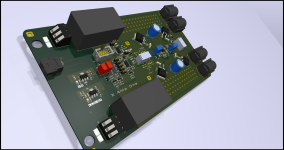
Hey, no not a dumb question, I split the AC mains connects to minimise any induction into the regulators also there is an intention to place some small signal
components in that area as well. I am looking at possibly powering from a DC source as well, but for now it is very quiet operation with the current design and layout. The board is 2 layers.
components in that area as well. I am looking at possibly powering from a DC source as well, but for now it is very quiet operation with the current design and layout. The board is 2 layers.
I see. Routing AC mains would be so much easier on a 4 layer board, as you would have nice shielding between it and small signal components.
Looking forward to what you'll cook!
Looking forward to what you'll cook!
Yes, I had considered 4 layers for that very reason as you mentioned, but chose 2 layers for now to test the idea out.🙂
- Home
- Holton Precision Audio
- OPA1622 based 4 x Outlet Headphone Amplifier