Is it possible ?
Hey, i was wondering if it is possible to use som of following components, for a D-class?..
Mosfet:
http://docs-europe.electrocomponents.com/webdocs/097a/0900766b8097ae0f.pdf
Amplifier for triangle wave and comperating:
http://docs-europe.electrocomponents.com/webdocs/0aa5/0900766b80aa53c6.pdf
Possibly this comperator:
http://docs-europe.electrocomponents.com/webdocs/0032/0900766b80032b90.pdf
Or can i use this as a "all in one":
http://docs-europe.electrocomponents.com/webdocs/0026/0900766b80026a9e.pdf
😕
i have mosfet drivers an fets..
You can use almost anything for class D. But why would you choose these? Your MOSFET limits supply voltage to 30 V, wich means approximately 24W @ 4 ohm. If you need only 24W, then there are truly one-chip solutions. And why would you use such an expensive OPA, when a comparator is cheaper and better?
components
what i have calculated i can get around 80-100watt in to 8 ohm at 30V if i use bridge..
30V^2 = 900
900/8ohm = 112.5watt
as for the op amp, it is not That expensive..
but what do you want to recommend?
what i have calculated i can get around 80-100watt in to 8 ohm at 30V if i use bridge..
30V^2 = 900
900/8ohm = 112.5watt
as for the op amp, it is not That expensive..
but what do you want to recommend?
Hmmmm.... I don't think so. 
You might squeek by with 50W RMS into 8 ohms with a 30V supply. That's not bad, plenty of power for most jobs. You'll need to keep the chips cool.
You might squeek by with 50W RMS into 8 ohms with a 30V supply. That's not bad, plenty of power for most jobs. You'll need to keep the chips cool.
...
okay..
i was thinking of half and full bridge.
what is the main factors that i should compare the N - P channel?
On resistance, rise/fall time ? and what is the margin max 10% off??..
okay..
i was thinking of half and full bridge.
what is the main factors that i should compare the N - P channel?
On resistance, rise/fall time ? and what is the margin max 10% off??..
what is the main factors that i should compare the N - P channel?
It depends on the gate driver, power level, and the quality demand. N an P channel FET's are completely different, so you can't expect too much.
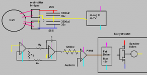
I think IRFZ24N and IRF9Z34N are well enough. I attached a simple schematic. In this circuit your OPA can be quite useful because of its high short circuit current. (But it's just an idea!) You have to change some values! (Gate-resistors and 100 ohm must be reduced significantly if you use AD818.)
Take special attention on supply decoupling, and ground plane, if you build it!
Attachments
reply..
Pafi..
I might have explained it wrong, how do i match a N and a P mosfet for a bridge 🙂..
the schematic that you made, i guess it is self oscillating?..
i have already made a test breadboard. looks like the pic i attatched,
i just need to know, where and how to add "dead time" ??
the op amp i use right now is lm833n, the carrier is around 120khz..
when i connect my 8ohm speaker, it actually sounds great..
Attachments
I might have explained it wrong, how do i match a N and a P mosfet for a bridge
For a bridge? Why do you think it is different from matching for a half-bridge?
You explained your question well for the first time, but the answer depends on some unknown things, as I said. Don't bother, there are more serious other problems!
the schematic that you made, i guess it is self oscillating?..
Yes.
i just need to know, where and how to add "dead time" ??
Between gate-driver and FET, or between comparator and gate-driver if your gate driver has 2 channels. How? R||D, C
In any cases you must disconnect two gates from each other! And you need level shifting between gate-driver and FETs.
when i connect my 8ohm speaker, it actually sounds great..
Where do you connect it, if power stage is "not yet tested"?
I dont think that matching a half bridge is different to a full bridge..
but shouldn't the N and P have almost same on resistance and same switching times or could all of that be taken care of with feedback?..
how i testet,
i have a "unused" amp in one of the chips so i just made that do the "dirty job" of driving the speaker, i know it is a bad solution, but just to test if it was working, it is clear that the opamp is lacking in current.
shouldn't the N and P have almost same on resistance and same switching times
This could have made things easier, but it's practically impossible. They are completely different. This because you have to match switching times by independent dead-time settings and/or reduce distortion by feedback. This way you dont have to use matched devices.
You have to decide if you chose pairs with the same resistance but very different speed/capacitance, or similar speed, but very different resistance. This decision must be made upon the rest of the circuit.
matching..
Okay.. thx 😀.. so i just have to find some N and P which is as close as possible..
the amp rating and voltage rating does not matter as long at it is greater than the supply voltage and so on..
as for my driver it is only a one channel, is that sufficient?..
and can you link me a easy dead time schematic that i can put in between opa and driver ?..
Re: matching..
Maybe, if you insert two level shifter and two dead-time circuit between gate driver and FETs.
You can't put it there, if you have only one channel of gate-driver! Think it over!
I think first you should learn basics of electronics. Or simply copy a well-designed circuit.
Sponkii said:Okay.. thx 😀.. so i just have to find some N and P which is as close as possible..
the amp rating and voltage rating does not matter as long at it is greater than the supply voltage and so on..
as for my driver it is only a one channel, is that sufficient?..
Maybe, if you insert two level shifter and two dead-time circuit between gate driver and FETs.
and can you link me a easy dead time schematic that i can put in between opa and driver ?..
You can't put it there, if you have only one channel of gate-driver! Think it over!
I think first you should learn basics of electronics. Or simply copy a well-designed circuit.
thx..
thanks for the links..
Pafi..
already 5 min after i saw my post i knew that i couldnt only do it with a one channel driver..
but i suppose that i could do it with 2 of the same kind, and add delay before each signal?....
thanks for the links..
Pafi..
already 5 min after i saw my post i knew that i couldnt only do it with a one channel driver..
but i suppose that i could do it with 2 of the same kind, and add delay before each signal?....
- Status
- Not open for further replies.
- Home
- Amplifiers
- Class D
- Op amp pwm design