Hi. I'm still a newbie at all this, but I've learned a lot by building a few guitar effects pedals. I'm hoping someone with more experience can suggest what might be wrong. This project is for a guitar onboard preamp, and I have encountered a strange problem. It's for the Bass-Treble module. It seems to have an output "ceiling". What do I mean? Well first, here's an intro to my project.
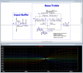
I pulled the filter design from an old application note (can't recall which one, I'll try to find it). But I have laid it out in LTspice, and tweaked the values to suit my needs. It's a "hinging" control, effectively a combination of two opposite-gain shelving filters, both having the same cutoff. It connects to a single linear pot, which in the middle position produces null effect (flat response). But turning it one way or the other will boost Treble and cut Bass, or vice versa. I wanted more Treble effect than Bass, and have balanced the circuit as such. So I finally got it to work fine in the sim (I know, that doesn't mean it'll work in the physical world, but it's a start).
To prevent interaction with the inductance of the guitar pickups, I have an initial unity-gain buffer that is fed directly from the guitar output. The buffer is implemented in one half of my dual op amp, and I used the other half to drive the filter. I added a resistor and capacitor between these stages - the resistor to insulate the op amp output from the load of the capacitor, and the capacitor for DC-blocking. The op amp is fed from a bipolar power supply that I built ... linear regulated +/- 15V. I connect its ground to the ground seen in the filter circuit on the op amp + input, which is also shared with the guitar signal ground.
The output has another resistor-capacitor pair, serving the same purpose as those between the buffer and filter stages. From there, I can go straight into the guitar amplifier. The actual design is to incorporate another stage (a midrange boost/cut circuit), and then an AMZ MOSFET booster (adjusted for unity-gain, serving as an output buffer). But for now, these are not at issue, and not included.
So what's the problem? I already said the Bass-Treble cicuit works fine, so that's not it. As I mentioned earlier, the problem is that my output level seems to have a "ceiling". When I plug into an amplifier, everything is fine, up to about 3.5 on the dial. Then nothing more happens. No additional volume. From 3.5 to 10, I get the same volume. It's not the amp - I've plugged the guitar straight in, and with just the input buffer in between, and it works fine. I have noticed one interesting thing - if I leave the guitar alone and listen carefully, there seems to be at that point of the dial a little bit of extra hiss. Dunno if this has a bearing, but it's too much of a coincidence, so maybe that'll be a clue to someone.
What have I tried? All of the following:
- test just the input buffer... it works fine
- remove the input buffer... no difference
- remove the coupling resistor and cap between the stages... no difference
- remove the coupling resistor and cap after the Bass-Treble stage... no difference
- follow with another op amp buffer identical to the input buffer... no difference
- follow with an AMZ MOSFET booster (unity gain).. no difference
- pull and re-insert all components from the breadboard, in case it's mangled in there ... no difference
- pull all components and move sideways two holes, in case it's mangled in there... no difference
- try different op amps (so far TL072, NJM2068, JRC4562)... no difference
- try a different pot... no difference
- try different resistors and caps in the Bass-Treble circuit... no difference
- oh, and I've tried it without the resistors Rbt_7 and Rbt_8. They're just there to allow me to use a B100k center-detent pot, and they adjust the circuit gain and the pot taper. Whether included or not, there's no difference in the problem.
I probed the Bass-Treble circuit at different locations (see labels on circuit diagram), and got these results:
A1, A2, A3, A4 - normal (Good volume at amp from 0-10. Buffered levels are marginally greater)
B - low volume, is filtered with pot rotation
C - normal volume
D - low volume, definitely filtered with pot rotation
E - medium volume, definitely filters with pot rotation (higher level than at D !!! But still way too low)
F, G, and H - low volume
(for all of the above, "low volume" refers to the "ceiling" effect I mentioned, of no increase at amp past 3.5/10)
So, can anybody point out the problem? I'm stumped (which in itself is not unusual, but it has put me at a standstill)
Attachments
You don't show any volume control, so how can we comment?
Also please repost the schematic without all the annoying labels and instead with actual parts values.
Also please repost the schematic without all the annoying labels and instead with actual parts values.
output ceiling?
does that mean:
What is the maximum output voltage?
If so, it is stated in the datasheet.
does that mean:
What is the maximum output voltage?
If so, it is stated in the datasheet.
Hi, thanks for replying.
JMFahey, there's no volume control showing because I'm not using one on the input. The guitar signal is the input, and it stays wide open. The volume that I refer to is on the amplifier... the amplifier volume level tops out at 3.5/10 on ITS volume dial, and nothing more from 3.5 to 10. Sorry, I can't repost until I get home, but the values are in the key. R1 and R2 (and R7 and R8) are 36k, R3 and R4 are 1k, R5 and R6 are 22k, the caps are 8.2n, and the coupling caps are 10u.
AndrewT, the output of the op amp is sufficient, as I tested just the input buffer stage, and it works great. In question is why the output of the second stage seems to "top out". That stage, as configured, does not seem to act the same.
I've considered that perhaps the circuit of the second stage creates a capacitive (or other impedance) load that the op amp doesn't like. But that's just a guess, and I really can't see why I get this strange behavior. Note that I have tried an additional op amp buffer between stage two and the amplifier. Help?
Not sure if this has anything to do with it, but some guitar amplifiers do use linear pots for their volume control (e.g. some recent Fenders). This is believed to be for 'marketing purposes'. When people try them in the shop, they give the impression that they are extremely loud as 'everything happens' by about 3.5 on the dial, and even on 1.5 they are blasting!
I do not have an idea of your Problem with the pot, but concerning the LTSpice simulation I assume it will come pretty close to reality. You should inspect the output signal with an oscilloscope to find possible instabilties / oscillations above the audio band.
probably not the issue but 10 Ohms isn't enough to isolate the TL072 from Cload effects - should be closer to 100 Ohms
the TL07x has really poor pull down, doesn't do well nearing the negative supply - can get oscillation bursts there 1st with Cload like cables
the TL07x has really poor pull down, doesn't do well nearing the negative supply - can get oscillation bursts there 1st with Cload like cables
" if I leave the guitar alone and listen carefully, there seems to be at that point of the dial a little bit of extra hiss." Possible ultrasonic oscillation. The only way to know for sure is to view the waveform with an oscilloscope.
Is your breadboard like the one at PB-103 Global Specialties | Mouser
If so, it is a distributed capacitance network that I think is unsuitable for analog circuit prototyping.
Is your breadboard like the one at PB-103 Global Specialties | Mouser
If so, it is a distributed capacitance network that I think is unsuitable for analog circuit prototyping.
Hi
Well, thanks to all for your input. The crisis seems to be over - at least for this point in the project. The problem appears to have been in the crappy little amp I have in my workshop just for testing purposes. It's a little POS Squier amp I salvaged out of a package a couple years ago. Apparently its input stage has some pretty cheap stuff in there. Because when I plugged it into my Fender Champ and Mesa Mark V, both of them seem to have no issues whatsoever. The amp volume controls operated in their full range of travel. And to boot, the circuit works exactly as I intended. Malcolm, I guess you were on the right track in suspecting the amp, and that pointed me at trying others.
Bill_P, good call on the breadboard. Yeah, that (sort of thing) is what do I generally use for workups. And yeah, I know they're crappy. I really like the term "distributed capacitance network" - I'll be using that. Generally, if I can get a circuit to work in general terms, I'll move as soon as I can to at least perfboard, so I can see what it really does.
jcx, good call on the resistors. I did try different ones, and they moved the effect up or down the dial a bit, without curing it though.
And Bill_P, I was indeed suspecting oscillation, due to that little hiss. Unfortunately, I don't have access to a scope of my own, just one I can borrow from work. As I suspect there may still be some in there, so I might get my hands on that scope and take a look. Or for now I might just try a ferrite bead in the circuit here or there, as I suspect it wouldn't hurt and might help. Thoughts?
Thanks all for your help. And I hope this thread lives on for others who are foolish enough to use a turd for a testing amp.
- Status
- Not open for further replies.
- Home
- Live Sound
- Instruments and Amps
- op amp output ceiling ???