You have to many variables to easily predict the switch on thump imo. The bias current of the 5532 would need to be measured because it determines the current that flows out of the opamp input pin. As you know looking at the data sheets, it varies from device to device by a wide margin. Also the setting of the volume control will alter the charge rate of the cap.
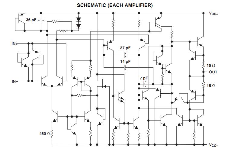
I can understand that, but as I mentioned previously, a MAX input bias current of 800nA does not explain a start-up voltage spike of 7V so something crazy is happening to that input bias current during start-up. Here's the NE5532 schematic. I don't really know enough to fully understand such a schematic 😛
9k1 is a very low value for Rin.
Can your source drive that?
Add a grounding resistor at the RCA input.
Add an RF filter at the RCA input.
Add an RF filter after the 1k on the +IN input.
Does the IC have DC gain = 1, or = ??
Is 9.1kOhm a low value? I would guess that a 32Ohm headset or earplugs is a far lower value (which are impedances that are normally plugged into cellphones, computer soundcards etc.). What will putting a ground resistor at the RCA input do? The amplifier has a DC gain equal the AC gain, that being x13.
the input resistor ensures that the input is referenced to signal ground, i.e. no unknown voltage sitting across the cap.
Discharging that voltage by plugging in a Source could blow your headphone.
Discharging that voltage by plugging in a Source could blow your headphone.
I can understand that, but as I mentioned previously, a MAX input bias current of 800nA does not explain a start-up voltage spike of 7V so something crazy is happening to that input bias current during start-up. Here's the NE5532 schematic. I don't really know enough to fully understand such a schematic 😛
What I think...the bias current and the input cap are only part of the problem. During power on and as the rails rise the circuit is in an unpredictable state... for an instant... as the feedback is being established and so on. If a differential voltage between the opamp inputs occurs (your cap pulling current from one and not the other) then the output swings hard over to one or other rail... you hear a thump or whatever... within a fraction of a second the feedback is stabilising and pulling the output back toward zero. Also... when "out of range" signals appear such as could happen at power up then internal junctions within the IC may conduct when normally they would not. There is no magic formula for this... its many things happening at once many of which are variables and will not be the same from one device to another.
Another factor in this design is incorporating the add on output stage. That will not conduct until the transistors have sufficient bias, the bias is dependent on the supply, the supply is rising, the opamp is trying to correct a moving target and in any case, until the add on part conducts correctly the feedback, which is fed from the add on is not established. Another possible problem area. How about a low value (experiment) between opamp output and main output to overcome the dead zone as the transistors are non conducting due to no bias.
The bottom line is that the amp has so far not been designed to allow silent switch on and off... and ensuring a good "user experience" should be just as much a part of a design process as the audio stages.
Sorry, that's not meant as a criticism, just an observation 🙂
I have no other answers for you I'm afraid.
It already has one, consisting of R4-R5-C7. Increasing the value of C7 will make it bias up slower or "softer."
Thank you. This is what JLLH mentioned elsewhere for a similar circuit:
"The loud speaker plop on switching on is avoided by DC coupling the NFB to the first transistor via R16. This causes the potential at the loud speaker output to rise fairly slowly as C charges. This arrangement reduces hum pickup on badly smoothed HT supplies...."
Last edited:
Thank you. This is what JLLH mentioned elsewhere for a similar circuit:
"The loud speaker plop on switching on is avoided by DC coupling the NFB to the first transistor via R16. This causes the potential at the loud speaker output to rise fairly slowly as C charges. This arrangement reduces hum pickup on badly smoothed HT supplies...."
The voltage at C7 is the bias voltage. If it rises slowly, then so does the output bias voltage.
It's really that simple. C7 also provides power supply noise bypass.
Variations on this circuit have been around for a long time. Since the direct coupled amplifier became popular, you don't see it anymore.
Great response, Mooly. I made yet another amplifier and this one had barely any audible pop sound at start-up so I see now that this varies greatly between amplifiers even though the design and PCB are the same. I'm going to wait with the output relays for now, I'll implement them if I keep having this pop sound problem.
One last thing about the offset voltage. I've been spending a lot of time trying to keep the offset at a minimum, implementing pots, trying cancel out the input bias currents etc. In this new design I wanted to have adjustable gain, but this will further increase the issue with the offset voltage. I've ordered a couple of new op-amps with considerable lower bias currents, but I'm not going to get 0V offset regardless. I was originally afraid of the ESR of electrolytic capacitors and it's tendency to increase with age (I want the output impedance to be as low as possible), but I see now that it should be possible to get electrolytics with an ESR well under 1Ohm. One issue though, electrolytics are polarized so how can 0V offset really be achieved with a dual-sided design?
One last thing about the offset voltage. I've been spending a lot of time trying to keep the offset at a minimum, implementing pots, trying cancel out the input bias currents etc. In this new design I wanted to have adjustable gain, but this will further increase the issue with the offset voltage. I've ordered a couple of new op-amps with considerable lower bias currents, but I'm not going to get 0V offset regardless. I was originally afraid of the ESR of electrolytic capacitors and it's tendency to increase with age (I want the output impedance to be as low as possible), but I see now that it should be possible to get electrolytics with an ESR well under 1Ohm. One issue though, electrolytics are polarized so how can 0V offset really be achieved with a dual-sided design?
If you AC couple the feedback return then you can implement a true gain control by making the lower leg of the feedback network (the resistor in series with the cap) variable. AC coupling the network means DC offset is unchanged with gain.
Electroylitics and tiny offsets aren't really an issue as long as the voltage across the cap is only a few millivolts. Myself, and I would always measure the actual voltage across such caps and fit them accordingly even if it means you have caps fitted one way in one channel and the other way around in the other channel.
If you equalise the input bias currents of any opamp then the offset should be low anyway 🙂
I feel stupid sometimes, why didn't I implement a cap in the feedback return path right away? Seems to remove almost all of the issues, effectively reducing the offset voltage by a factor of 13 🙁 My next PCB will have this cap installed 🙂
Took 58 additional posts before appreciating what was said in post #10 and numerous of posts following. 🙂
Last edited:
Took 58 additional posts before appreciating what was said in post #10 and numerous of posts following. 🙂
How were those posts related to the topic of this thread?
Oh sorry, this thread was not about a loud thump then? What was it about?
I tried to find and I asked for the connection between the offset and the thump sound several times, but found none. Increasing or decreasing the offset did nothing to change the thump sound.
I think I am correct to say that a large thump at power up or under unusual circumstances power down is normally caused by an instantaneous input differential when power is applied and the DC gain being high. Now an instantaneous off-set can be caused by PCB layout and in particular the grounding system used inside the amp.
Let us assume that your headphone is connected to ground and further on the same track is the bias resistor of an input. As you power up, the current flowing through the speaker inductor could instantaneously pull the ground to the positive or negative rail and being amplified by the op-amp causes an instantaneous spike that lasts until all the lumped elements stabilize and ground returns to its normal value which is half of the supply voltage.
By decoupling the feed back as mentioned in earlier posts would lower the DC or low frequency gain and hence reduce the amplitude of the spike appearing at the output - but do try and find if the problem is not in your layout and or wiring.
I have encountered many microprocessors resetting when an inductive load is present and driven to the same grounding as the processor.
Last edited:
I think I am correct to say that a large thump at power up or under unusual circumstances power down is normally caused by an instantaneous input differential when power is applied and the DC gain being high. Now an instantaneous off-set can be caused by PCB layout and in particular the grounding system used inside the amp.
Let us assume that your headphone is connected to ground and further on the same track is the bias resistor of an input. As you power up, the current flowing through the speaker inductor could instantaneously pull the ground to the positive or negative rail and being amplified by the op-amp causes an instantaneous spike that lasts until all the lumped elements stabilize and ground returns to its normal value which is half of the supply voltage.
By decoupling the feed back as mentioned in earlier posts would lower the DC or low frequency gain and hence reduce the amplitude of the spike appearing at the output - but do try and find if the problem is not in your layout and or wiring.
I have encountered many microprocessors resetting when an inductive load is present and driven to the same grounding as the processor.
I have a star grounding. The gnd from the pot, inputs and output all come together to the same exact point. I guess in theory there should be some crosstalk between the channels since the ground path from the biasing of one channel joins the ground path of the biasing of the second channel further down the line. My guess is that this tiny current can't cause enough of a voltage drop to actually cause audible crosstalk.
I'm going to use a different op-amp with way lower input bias current. This will allow me to use higher value input resistor and feedback resistors thus allowing me to use a smaller value input cap. If I run into this thump sound again, I'm going to implement some reed output relays.
One kind of unrelated question though. I have in the past experienced that one of the joint to one of the big current reservoir caps simply broke, maybe caused by physical stress or a temperature difference. This is a very big deal as it leads to huge 100hz spikes on the output, easily capable of destroying a pair low impedance headsets. I've now used thicker traces and bigger pads for the caps, but I'm really afraid of something like this happening again. It's not very tempting to plug in a $2000 headset when there's a possibility for the amp to simply kill it in the event of a failure. How do high-end amplifiers prevent such a thing from happening in the event of a cap failing?
- Status
- Not open for further replies.
- Home
- Amplifiers
- Solid State
- Op-amp input, class AB output. Loud thump sound