I have this 4-channel "Color Organ" in a previously finished project.
And it performs nicely to animate the colored lamps to the music.
Yellow=trumpets - Red=vocals - Green= lower vocals - Blue=bass notes.
However, one thing bugs me....
The lowest frequency just isn't low enough for my tastes.
The "Bass" section of the IC activates higher than I'd prefer, and I'm in a bit of confusion on making it activate at a lower frequency.
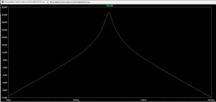
As shown, it's around 300Hz.
I have tried 0.1uf caps in place of the 0.47uf, but the lamp doesn't even activate at all. ( actually jumped the .047's with another .047)
I want it to center around 80 to 150Hz.
Anybody here have any positive (not guesses) ideas on how to mod the existing circuit (caps, resistors)?
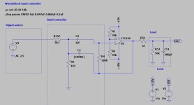
This is the circuit.

And it performs nicely to animate the colored lamps to the music.
Yellow=trumpets - Red=vocals - Green= lower vocals - Blue=bass notes.
However, one thing bugs me....
The lowest frequency just isn't low enough for my tastes.
The "Bass" section of the IC activates higher than I'd prefer, and I'm in a bit of confusion on making it activate at a lower frequency.
As shown, it's around 300Hz.
I have tried 0.1uf caps in place of the 0.47uf, but the lamp doesn't even activate at all. ( actually jumped the .047's with another .047)
I want it to center around 80 to 150Hz.
Anybody here have any positive (not guesses) ideas on how to mod the existing circuit (caps, resistors)?
This is the circuit.
Do you mean that you want to change the center frequency as well as the quality factor, so the response over the 248 Hz to 350 Hz range shifts to 80 Hz to 150 Hz?
If you just want to change the center frequency while keeping a 6 dB bandwidth of about half an octave, then it's simple: the center frequency is inversely proportional to the capacitance, so 150 nF capacitors should get it in the desired range.
What I don't know, is whether the 0.47 uF should also be increased by about a factor of three. Is it 0.47 uF in all the other channels or does it depend on the center frequency?
Last edited:
Circuit seems designed ok. Play around with this simulator.
http://sim.okawa-denshi.jp/en/OPtazyuLowkeisan.htm
http://sim.okawa-denshi.jp/en/OPtazyuLowkeisan.htm
Check this out: Filter Design and Analysis
Scroll down the page to "Multiple Feedback Filters" and have a ball!
Mike
Scroll down the page to "Multiple Feedback Filters" and have a ball!
Mike
If the circuit isn't triggered with 0.1µF caps, it probably means that the music program does not contain enough LF components.
Another possibility is that the 0.47µF cap to the doubler is too low to trigger the triac
To increase the gain, change the 3K3 to 1K5 ratio, whilst keeping the parallel value identical: for example, swap the 1K5 and 3K3.
To extend the LF triggering range, increase the 0.47µF to 1µF or 1µ5, or even higher. If it doesn't work, it simply means that your program has insufficient bass contents
C2 increase to 1uF seems to pull the center frequency down.
The asc-file is the LTSpice schematics.
The asc-file is the LTSpice schematics.
Attachments

Sorry, I meant 0.047, my earlier was a missprint.Do you mean that you want to change the center frequency as well as the quality factor, so the response over the 248 Hz to 350 Hz range shifts to 80 Hz to 150 Hz?
If you just want to change the center frequency while keeping a 6 dB bandwidth of about half an octave, then it's simple: the center frequency is inversely proportional to the capacitance, so 150 nF capacitors should get it in the desired range.
What I don't know, is whether the 0.47 uF should also be increased by about a factor of three. Is it 0.47 uF in all the other channels or does it depend on the center frequency?
And each "band" uses a different capacitance and resistor layout.
The other bands are fine.
Indeed, I want to stay in basically the same bandwidth and sensitivity area.
Just closer to where the real bass is, not at 300Hz
Last edited:
My mistaken typing -I meant 0.047 as in the schematic, not 0.47If the circuit isn't triggered with 0.1µF caps, it probably means that the music program does not contain enough LF components.
Another possibility is that the 0.47µF cap to the doubler is too low to trigger the triac
To increase the gain, change the 3K3 to 1K5 ratio, whilst keeping the parallel value identical: for example, swap the 1K5 and 3K3.
To extend the LF triggering range, increase the 0.47µF to 1µF or 1µ5, or even higher. If it doesn't work, it simply means that your program has insufficient bass contents
There is a 0.47 uF capacitor after the op-amp, I think Elvee means that one, and that's also the one I meant in my last paragraph.
Thnak you madis64.C2 increase to 1uF seems to pull the center frequency down.
The asc-file is the LTSpice schematics.
I was wondering if you could provide me with info that if I changed C1, C2 caps from 0.047uf to 0.068uf, what the results would be.
Why are you insisting on increasing both capacitors in exactly the same way?
My layman reasoning says that one is the gate keeper for the lowest frequencies and the other one is determining the upper limit of the filter.
Edit:
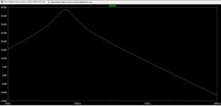
Anyhow, C1/C2 0.068uF graph would be like this.
My layman reasoning says that one is the gate keeper for the lowest frequencies and the other one is determining the upper limit of the filter.
Edit:
Anyhow, C1/C2 0.068uF graph would be like this.
Attachments

Last edited:


Just ask mooly to help you starting up with LTSpice 😉
It is a bit rough when starting up but after that it can save you a lot of time.
Edit:
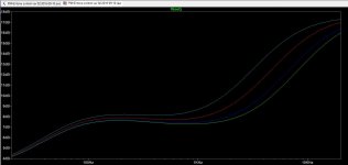
when I decided that Marantz PM-63 tone control was not according to my preference then modelling it clearly indicated which way to go.
It is a bit rough when starting up but after that it can save you a lot of time.
Edit:
when I decided that Marantz PM-63 tone control was not according to my preference then modelling it clearly indicated which way to go.
Attachments
With a standard filter topology like this, you can simply use a dedicated tool, very easy.
http://sim.okawa-denshi.jp/en/OPtazyuLowkeisan.htm
http://sim.okawa-denshi.jp/en/OPtazyuLowkeisan.htm
Not really: the center frequency is determined by the geometric average of the two caps, and their ratio affects the gain/Q of the filter. Small alterations of the ratio are not going to change things very much: 47n +47n will be almost identical to 39n + 56n, except the gain/Q is maximal for the balanced situationMy layman reasoning says that one is the gate keeper for the lowest frequencies and the other one is determining the upper limit of the filter.
If you have 0.047uF in the input path of any amplifier then you are restricting the lower frequencies (from entering the amplifier stage) more than having 1uF there - do we agree?
For an amplifier, maybe; filters are a different breed of cats and obey they own rules.
You can make simulations to corroborate or infirm your hypothesis, but basically you should find that my statements are true: geometric average and gain are the governing parameters
You can make simulations to corroborate or infirm your hypothesis, but basically you should find that my statements are true: geometric average and gain are the governing parameters
- Home
- Source & Line
- Analog Line Level
- OP AMP circuit mods?