Hi guys,
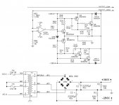
Would need your help on how to improve this Op Amp buffer/amplifier with quasi-complementary output. I've had several blown driver and output transistors (Q3, Q4, Q5 and Q6) and with likelihood that the resistors (R74, R75, R76 and R79) getting toast as well. I've read several threads related to quasi-complementary and would like to seek your advice regarding improving this design.
1. Component upgrade. Better driver/output transistors combination. How will it affect the resistor values?
2. Using a Baxandall diode/JLH diode. All amplifiers of this type I saw have the NPN driver/NPN output transistor connected to the positive supply and the PNP driver/NPN output transistor connected to the negative supply. A resistor, diode and capacitor is connected between the output and emitter of the PNP driver transistor. In my attached image. Should I connect the resistor/diode/capacitor between positive supply and emitter of PNP transistor?
3. Upgrading the P/S to a capacitance multiplier?
Thanks in advance for your comments and reply.
Nuki
Attachments
Why are you using the 2N6259?
Why not use the 2N3055/MJ2955 pair?
That circuit looks like it has a lot of room for improvement.
Why not use the 2N3055/MJ2955 pair?
That circuit looks like it has a lot of room for improvement.
Hi djk,
The 2N6259 is the original part.
Actually I've tried MJ15024 with moderate success. I think that the pre-driver and the driver needs to be upgraded to more modern parts. The pre-driver 2n2222a and 2n2907 have a different resistor in their collectors, 510 ohms and 1kohms, why this is so? If I change to a really complementary pair, will they be equal? What value? Same with the 2n5320/22 pair, just curious why is the placement of the 33 ohms different? Most quasi-complementary I've seen don't have this resistor from driver to output transistor.
Thanks.
Hi Jcx,
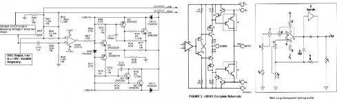
You mean like a power op amp that would replace the LF412 and output buffer/amplifier?
Actually I just read the datasheet of an LH0101 and the op amp + output amp arrangement is similar except that the output is full complementary. This too is obsolete though.
You mean like a power op amp that would replace the LF412 and output buffer/amplifier?
Actually I just read the datasheet of an LH0101 and the op amp + output amp arrangement is similar except that the output is full complementary. This too is obsolete though.
The problem, as jcx hints, is that the whole circuit is both obsolete and sub-optimal. It would be better to start again with a popular forum design from scratch, whether you reuse parts or not. Those power supply rail voltages would seem OK for some larger chip-amps which would perform much better than the attached schematic circuit. It would probably cost less than the necessary mods and still be much simpler by just plug and playing a cheap kit.
Hi Ian,
I was toying with the idea of implementing a discrete design based on the LH0101 and utilizing the same or better transistor combo but don't have the design skills to do it. The board which houses the amplifier also contain the adjacent DAC circuit and associated logic. This is then housed in a constrained module. So putting a power chip amp is not possible at this time.
So going back to the 1st thread, optimizing the circuit which you mentioned is the way to go, better transistor combo or some circuit trickery will do. I hope to learn a bit of designing in the process, I think.
Thanks.
The circuit as drawn is... strange.
Where is the +/- 12V coming from? The circuit has too many problems. Quasi-complementary is rarely used now other than for junk-box amplifiers where somebody is scrounging around to build an amp from available parts or for some other unusual reason.
The best thing really is to forget this circuit and pick another one.
What is the signal source? What is the impedance of the output transducer (speaker)? How much power output is really necessary?
Is stereo required?
If you answer these questions we can recommend a circuit that will be more educational or cheap. If you make your objective understood it will make for a more focussed recommendation.
I see you have partially answered some of the questions in a cross-post.
Post a picture of the space into which the amp must fit if you can and answer the questions to the best of your ability. It may still be possible to remove the existing amplifier components and stick in a new board with doublesided tape.
Also post details of any preceding circuit.
Post a picture of the space into which the amp must fit if you can and answer the questions to the best of your ability. It may still be possible to remove the existing amplifier components and stick in a new board with doublesided tape.
Also post details of any preceding circuit.
Last edited:
monolithic audio power amp chips - check the chip amp forum - LM3886, LM4780, TDA7293 are all pretty complete amps, have many project articles - sometimes known as "Gain Clones"
most have output protection, thermal overload protection circuits built in too
most have output protection, thermal overload protection circuits built in too
The circuit you show isn't complete, but good enough to see whats going on.
The big problem with this arrangement is that there is gain in the output stage. This is difficult to stabilise and frequently causes oscillation. That is probably why you have had blown output transistors. There's also no emitter resistors so I expect the amp has gone into thermal runaway at times too.
I agree with the other posts here - if you are looking for a replacement amp to fit in a limited amount of PCB space, you should use a chip amp such as LM3886. You're not going to be able to build anything discrete that is as compact and reliable as those.
monolithic audio power amp chips - check the chip amp forum - LM3886, LM4780, TDA7293 are all pretty complete amps, have many project articles - sometimes known as "Gain Clones"
most have output protection, thermal overload protection circuits built in too
Hi guys,
To answer your earlier posts.
1. +/-12V supplies for op amp and DAC are from 7812 and 7912 regulators.
2. I've simplified the amplifier to include the op amp inputs. The DAC outputs a sinusoidal wave 0 to 10V/0 to -10V, direct coupled. For a 4 ohm load, the max current is 1.5A and through R60 is sensed from the output.
3. The damper circuit samples the output and when the voice coil stops, generates opposite and decaying wave. Fed back to + input of op amp. Capacitor coupled to prevent DC.
4. As for the output circuit with gain, I find similarity to LH0101.
5. Am I correct to say that the op amp just buffers the DAC output. The quasi-amplifier is just a voltage to current converter?
6. Is is possible to remove the quasi-amp gain and bring it outside the op amp + quasi-amp like the Walt Jung composite op amp + buffer? My problem is how to integrate the various resistors at the op amp inputs.
Attachments
- Status
- Not open for further replies.
- Home
- Amplifiers
- Solid State
- Op Amp buffer/amplifier, quasi-complementary, need advice.