Hello
I wentto the solid state Forum, i will try here maybe it's more guitar friendly....just kidding.....i did get some help over there. Well here goes......iam not anti-power tube but why kill el34s and 6l6s by overdriving them so, i want to build a mosfet power amplifier that has a op-amp at the front-end. Now, i was told u could use a power IC as op-amp and this sounds good but iam not an amplifier Guru.......i need a schematic. I use a tube pre amp to get overdrive sound and clean tone 12ax7 don't cost that much. The op amp based mosfet power amplifier will be the muscle in the rig 150 to 250watta side....and no power tube to replace........Something like a Tube Works Mosvalve 942 power amplifier......they don't make those now. I play guitar and i like the Blues-rock- jazz-fusion type sound........Hendrix meet Albert King at coltrains house.....type sound......so if anyone has aschematic.....please step forward.........thanks
less componts in a power amplifier less headach
If it's a simple amp you are after and your power desire is more than 100W you can't use a chip as the voltages required will be too high. IMO using a chip front end requires so much additional circuitry it's not worth it.
Take a look at ESP Project 101. sound.au.com
Take a look at ESP Project 101. sound.au.com
Booth-strap
Hi richie00boy
Well if i use a low voltage op-amp i can boot-strap the supply lines of the op amp to get +/- 15 voltage for op-amp than i can use any voltage to power the mosfets output section....no problem. That is to get high voltage to the driver and mosfet power section.
Hi richie00boy
Well if i use a low voltage op-amp i can boot-strap the supply lines of the op amp to get +/- 15 voltage for op-amp than i can use any voltage to power the mosfets output section....no problem. That is to get high voltage to the driver and mosfet power section.
Are you sure you know what a bootstrap is? You are talking about a step down not a bootstrap 🙂 Moot point anyway. The output stage will be required to have gain and this is what makes things complicated. Trust me, it's not so easy 🙂 P101 is a good amp and about as simple as they get, take a look 🙂
Bootstrapping ???
richieooboy
Sorry for the terminology mix-up but what i ment was using transistors to match the low suppy voltage of a op-amp.anyway the amplifier you pointed out i have seen. I have the Randy Slone book on high power amplifiers and it has many many source-follower mosfet power amplifiers in it. Iam loking for something in aop-amp front-end design. This would feed apair of driver that would feed the mosfet output section. Iam no rocket scientist...they are down the coast a bit.......just guitar player
Now three of us are confused
I am not clear about what you are looking for. You say frontend for a mosfet amp. You want an FET input stage? Much better than OP-amps as far as tone goes. You already have a mosfet power-section design you like? (I love TubeWorks) Please clarify as I think you are just looking for a nice input/driver stage. By the way, there are tons of TubeWorks amps out there for sale. They are rugged and easy to fix, should they break. I use them for EVERYTHING from PA to bass. I believe Genz-Benz is still making a few of them.
I am not clear about what you are looking for. You say frontend for a mosfet amp. You want an FET input stage? Much better than OP-amps as far as tone goes. You already have a mosfet power-section design you like? (I love TubeWorks) Please clarify as I think you are just looking for a nice input/driver stage. By the way, there are tons of TubeWorks amps out there for sale. They are rugged and easy to fix, should they break. I use them for EVERYTHING from PA to bass. I believe Genz-Benz is still making a few of them.
not confused
Iam just looking for a schematic for a mosfet power amplifier that has three stages. a op amp input stage ,alevel shifting stage and amosfet output stage....very simple set-up and low part count.I want to build it my self....i built most of my gear. I know there is lots of Tube Works stuff out there but....i like diy
I checked out Genz-Benz site they no longer make Tube Works amplifiers....to bad......its good stuff.
A long time ago Elektor published a circuit that used an opamp input driving IRF p / n channel fets. It ran rails of around +/- 35 volts with zener derived voltages feeding the op amp. I think it provided an estimated output power of about 70watts into 8 ohms and 120 watts into 4 ohms.
From what I recall the circuit could be modified to handle +/- 50 or 60 volts with extra FETS to handle the power you are talking about.
I'll look for it tonight (10 hours time). In the meantime you may want to send me an email.
Cheers
From what I recall the circuit could be modified to handle +/- 50 or 60 volts with extra FETS to handle the power you are talking about.
I'll look for it tonight (10 hours time). In the meantime you may want to send me an email.
Cheers
Elektor circuit
quasi
this amplifier in the Elektor magazine sounds like what iam looking for.....finally.......thanks
quasi
this amplifier in the Elektor magazine sounds like what iam looking for.....finally.......thanks
You might also like to take a look at White Noise Audio as they do a kit 250W amp like what you desire (MOS250).
Although making a discrete amp really is no more complicated than using a chip front end 🙂
Although making a discrete amp really is no more complicated than using a chip front end 🙂
Well here it is ...but,
10,000 apologies, not quite as powerful as I thought it was. The cct does however make a power upgrade fairly straightforward.
Main changes will be
1. changing the transistors specified to higher voltage types I.e. BC546 and BC556.
2. 1 watt zeners and higher value resistors feeding the base of the regulator transistors.
3. Paralleling extra FETS with source resistors to handle the higher power.
4. Adjusting components of the biasing network around T3 and T4.
Cheers
PS the amp should be considered ok for guitar use but probably not good enough for Hi-Fi. I tend to agree with Richieboy, a discreet amp would not be much harder to build and provide stacks of power.
Attachments
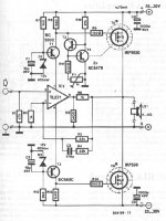
Elektor Amplifier
Hello qasi
No apologies needed at all....this is great i can upgrade this amplifier by increaseing the power supply and paralleling more mosfet (Hitachi mosfets don't havethermal-melt down like IRF) In the USA IRF are cheap but they are not matched like Hitachi mosfets.yes, i will increase the value of some resistors and their wattage,Zener wattage....etc.
Iam curious.....why would this amplifier not be good for Hi-Fi.
..oh richieooboy thanks for the info onthe Mos250.
Again.......THANKS for your Help.....Peace
IMHO....not for good Hi-Fi because
1. The drive impedance for the output stage is rather high. The gates are tied by a 1k4 resistor and this means an idle drive of less than 3 milliamps. I would rather see this around 15mA through a 270 ohm resistor.
2. The zeners on the transistor regulators will be a source of noise. I have tried zeners in my amps before and have always been dissapointed.
3. The TL071 could be replaced with something better.
Anyway I would try to stick to the IRF devices. The circuit has built in thermal compensation via T4 (mounted on the heatsink) so thermal runaway should not be an issue. The IRFs will have a lower Rds-on then the Hitachis so at full power will be more efficient. You could use 2 x IRFP240 and 2 x IRFP9240 and end up with a powerful and reliable amp.
Please let us know how it went if you build it.
Cheers & Good Luck
Adjusting componets of biasing network
quasi
I plan to use a power supply of +/-55 volts and 3pairs of mosfets to get an output of about120watts. I would like to know what value i should use in the biasing network for componets R10,R11,P1 and will i have to change T3&T4 value or do they stay the same. I have a tranformer the is 625VA i think.I will makethe other changes you pointed out too. As for the Hitachis mosfets i will replace them with the IRFP240 &IRFP9240....idid't know about the rds on thing......u say they are more efficient at full power......thats good. I will replace the regulators transistor with BD139&BD140...... I know this is overkill.......but it won't hurt.Later i can switch out the TL071 for something better. If u have anymoreideals.....please let me know. thanks........if this amplifier works i will build a 250watt per channel monster. Peace
(3IRFP240&3IRFP9240)
Biasing output mosfets
I forgot to ask about biasing the output mosfets. Do i use a amp meter to set the mosfets bias by removing one of the power supply rail fuse to take amperage reading.......if so how many ampshould i bring on with the bias pot............no Amplifier Guru.
I forgot to ask about biasing the output mosfets. Do i use a amp meter to set the mosfets bias by removing one of the power supply rail fuse to take amperage reading.......if so how many ampshould i bring on with the bias pot............no Amplifier Guru.
After looking at it properly I suggest ....
After looking at it again I suggest the following, based on supply rails of +/- 55 volt rails.
Change R7 and R12 to 5k6 (5,600 ohms) and leave D1 and D2 as 400mW zeners
The voltages across T1 and T2 will be up to 40 volts. A BC550/560's Vceo is 45 volts so it may be ok. I would not use BD139/140 here beacuse this transistor needs to be a lower noise type. If 5 volts spare is not enough comfort for you then use a BC546 / BC556. (Pray the zener never goes open cct.)
The voltage across T3 will be around 40 volts so a BC546 will be the best choice here. There is very little voltage across T4 but you may as well make that a BC546 (cheap), then again a BD139 would be easier to mount...so up to you.
Change R8 & R13 to 1k5 (more common)
R5 simply provides a load for the opamp, you can use 220 ohm here which again is a more common value.
Try leaving the biasing network R11 & P1 as it is but make P1 a multi-turn type.
Because of your higher rails I would give the amplifier more gain by changing R3 to 33k.
Of course C5 and C4 should be rated to at least 63 volts.
To set up the amplifier do not try to measure the current directly with an amp-meter. If the amp is faulty you will lose your FETs.
Without a load connected to the output insert 100 ohm 5 watt resistors in both power supply feeds and measure the voltage across one of them. Adjust P1 to get a voltage reading of 10 volts. All being well replace these with 10 ohm resistors (1 watt) and fine tune P1 to get 1 volt. You have now set the idle current to about 100mA, most of which will be flowing through the output FETs. If you want more bias current just remember that 1 volt = 100mA through a 10 ohm resistor.
That done replace the resistors with fuses, connect your speakers and enjoy the music.
Cheers
PS. Your choice of a 625va transformer is cool. You will need AC voltages of around 39 volts. Your capacitor bank should be no less than 20,000uF per rail.
PSS I apologise if I've told you how to suck eggs.....
Cheers again and good luck.
Just to add that 2 pairs of MOSFET output devices will be more than enough to handle 120W.
Also, the transistor you use for bias generator should be mounted on the heatsink and it will be quite sensitive as the output stage has gain. In fact the amp may be difficult to stabilise all round, but have a go if you want 🙂
Also, the transistor you use for bias generator should be mounted on the heatsink and it will be quite sensitive as the output stage has gain. In fact the amp may be difficult to stabilise all round, but have a go if you want 🙂
Biasing output mosfets
It's early....here
quasi
Iwill makeall of the adjustment you pointed. I Plan to go overkill on the heatsink for the amplifier plus use a fan tunnel because it being a guitar amplifier.....will live a stressful life. iwill build clip,over temp,and turn-on delay.....maybe a limiter circuit....etc. being it is a non-tube amplifier i will try to keep clean(not overdrive the power amplifier) by using a tube pre-amp to get overdrive tones.....using a master volume control......this should prolong the life of the power amplifier somewhat.
Oh...back to biasing the mosfets, isitpossible to bias them by reading the voltage through the source resistors also.......i mean hooking a meter across one of those resistor thatsin- line with the mosfet source?....just wondering like i say iam no GuRu of the amplifier.
THANKS for your knowledge and help.........iam collecting componet now ..but i shall keep u updated as i bumble along.....as you say
Cheers
PS...richieooboy iknow about mounting the t4onone of the power mosfet on the main heatsink....but thanks
Yes you can use source resistors, 0.33 ohms 4-6 watts I suggest. Then use ohms law (I=V/R) to work out the current through them. You want about 50-100 mA per pair.
- Status
- Not open for further replies.
- Home
- Live Sound
- Instruments and Amps
- op-amp based mosfet power amplifier for guitar rig