This is my headamp. Its my own design and using for over one year...
Its DC coupled but I've never measured over 4mV on outputs. It can drive both 32 and 64R headphones. Its 100mA biased and works in Class A. Now it works for an Ultrasone DJ1. And I am very happy with its sound!
Recommended 😀
An externally hosted image should be here but it was not working when we last tested it.
Its DC coupled but I've never measured over 4mV on outputs. It can drive both 32 and 64R headphones. Its 100mA biased and works in Class A. Now it works for an Ultrasone DJ1. And I am very happy with its sound!
Recommended 😀
Sorry Lineup, I should have been more specific. I am going to build a MOSFET based amp as opposed to an OP AMP cct.
zekeres Driver headphone amp
Also, I (stupidly) posted the wrong link for the first PSU. It should have been this one.
http://www.maplin.co.uk/Module.aspx?ModuleNo=96864&DOY=28m8
Regards,
Chris
zekeres Driver headphone amp
Also, I (stupidly) posted the wrong link for the first PSU. It should have been this one.
http://www.maplin.co.uk/Module.aspx?ModuleNo=96864&DOY=28m8
Regards,
Chris
zebra100 said:Sorry Lineup, I should have been more specific. I am going to build a MOSFET based amp as opposed to an OP AMP cct.
zekeres Driver headphone amp
Also, I (stupidly) posted the wrong link for the first PSU. It should have been this one.http://www.maplin.co.uk/Module.aspx?ModuleNo=96864&DOY=28m8
i know .. maybe you havent even read my 2 posts above ????????????
http://www.diyaudio.com/forums/showthread.php?postid=1594136#post1594136
shame on you!
Well, I finally have one channel working and it sounds awesome. Very detailed and clear. I can't comment on soundstage yet as I only have one channel. The other channel shouldn't take too long to do because I ironed out all the issues on the initial build. It doesn't go very loud. I am using a cheap 100k pot and some old Sony MDR-CD280 headphones (24 ohms/ 98dB). When I finish the other channel, I will get some better specification headphones to test it with.
I have used a modified cct from the original design. I went with a 13.8v psu for now and used an LM317 as a ccs with 250mA. The MOSFET does run quite warm, but not too hot.
Thank's for all the information guys.
Can't wait to get it finished.............🙂
I have used a modified cct from the original design. I went with a 13.8v psu for now and used an LM317 as a ccs with 250mA. The MOSFET does run quite warm, but not too hot.
Thank's for all the information guys.
Can't wait to get it finished.............🙂
You could try to lower the 250 mA current supplied from the LM317.
0.250 Ampere (1,25V/5ohm ) where two paralleled 10 ohm make one 5ohm.
As I recall it, IRF510 (or IRF610) works quite well at around 100 mA. And this level is well more than what 16 or 24 ohms or 32 ohm Phones will need. ( And of course even if impedance is higher, like 100 ohm )
Using the LM317 and two parallelled 22 Ohm/0.25Watt metalfilm resistors, will give you 1.25V / 11 Ohm = 113.6 mA Class A current.
I have designed/built one HP-amplifier for 32 ohm.
I set the Class A current in output ~90 mA in my prototype.
It it worked very well. I used one bipolar BD139 (TO-126) for my output. With a very small heatsink.
This amp have similar power supply = 12.0 Volt DC. Regulated by one 7812 3-pin IC.
To make it very clean supply.
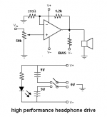
You could try the simple design. This sch. with good opamp like LME49860 would match or at least very close to top class headphone amp (you name it) with 32R headphone. 🙂
I recommend using NiMH battery and forget about the bias for now. 😉
If you got too much hiss, try 1k/5k or even 100k/500k (or something between) instead of 250R/1K
I recommend using NiMH battery and forget about the bias for now. 😉
If you got too much hiss, try 1k/5k or even 100k/500k (or something between) instead of 250R/1K
Attachments
It will work.
And be real hi-fi 🙂
When using CD-Player output and Gain=5, like you do
with your LME49710, LME49720 or LME49870 or LME49860
this would suit most anything between impedance 32 - 300 Ohm
32 Ohm phones, like Grado Hi-fi http://www.gradolabs.com/
and phones with 300 Ohms impedance
For example Sennheiser HD600, Reference Class
http://www.stereophile.com/headphones/408/
http://www.sennheiserusa.com/newsite/productdetail.asp?transid=004465
Amp finished, and it sounds damn fine. The modules are fitted into my passive pre for my Gainclone. I have fitted a selector switch to select between power amp and headphone output. It's powered by the 13.8v/3A Maplins psu for now.
It's had a good few hours at full tilt and the treble has calmed down nicely. I am testing it with a pair of Sennheiser HD565 ovation, which are very nice sounding headphones. What a difference over the headphone out socket on my NAD amp, even with the cheap off board PSU.
With the Dave Gilmour CD I am testing it with at the moment (Live recording), the sound stage is wide and deep. Bass is full and well controlled. The midrange is full of detail but quite neutral. The treble is crisp and detailed, and not fatiguing. It's a definite improvement over my main amp. I am most impressed with the bass. The sound I expected was more of a blurring of notes at the top end and muddying of the sound at the bottom end, with a decent mid range, but this just blows me away. It produces individual notes with ease. A very engaging listen.
I didn't think that a single MOSFET was capable of producing this kind of sound. How wrong can you be? The output caps I used were 470uF Silmic II's, bypassed with Wima 1uF's. I think they are perfect for this application. I don't think I need to fiddle with the design at all. DIY Nirvana. I had to fiddle about with my Gainclone design before I was happy with it, but this has hit the spot first time.
Thank's for all the advice guys.
zebra100 said:
I didn't think that a single MOSFET was capable of producing this kind of sound. How wrong can you be?
The output caps I used were 470uF Silmic II's, bypassed with Wima 1uF's. I think they are perfect for this application.
I don't think I need to fiddle with the design at all. DIY Nirvana. I had to fiddle about with my Gainclone design before I was happy with it, but this has hit the spot first time.
Thank's for all the advice guys.
>>> I didn't think that a single MOSFET was capable of producing this kind of sound
I have seen people express the same before. So, is certainly no joke.
Congratulations 😎 Well done, zebra100
New project ideas. After christmas and in 2009 maybe? Anything in pipeline?
Or Maybe just relax and enjoy the fruits of your work:
maybe ...
Play I Some Music, Dis a Reggae Music
Bob Marley - Music Video:
http://www.youtube.com/watch?v=WKowJMhdmDU
😎 😎
Thanks Lineup.
For my next project I might have a look at making some speakers for the Gainclone. Maybe some full range drivers, or somthing a little more exotic. Then maybe a DAC to complete the package. I'll have to wait until after christmas though, as most of my spare time this year has been taken up doing one hifi project or another. I'm more than happy to just listen to the music for now.
😀
- Status
- Not open for further replies.
- Home
- Amplifiers
- Headphone Systems
- OP Amp based headphone amplifier.