In response to posts looking for info about transformers, I thought i would bring all these together!!
http://www.valveheart.com/theory/transformer.html
http://www.geofex.com/Article_Folde...des/xformer.htm
http://members.tripod.com/richard98...former_math.htm
http://www.turneraudio.com.au/output-trans-theory.html
http://europa.spaceports.com/~fishbake/ot1/ot.htm
http://www.magnequest.com/mq_magnetics.htm
all sorts of info. in the MQ forum, too, do some searching
Feel free to add your own!!
May make sense to make this a sticky as there are all sorts of questions that crop up.
Originally posted by Mike LaFevre
[once you remove the dc current from the primary of the OT (either SE or PP) then the copper current density is made much better because you don't have the heating effect (and I squared R losses) that accrue from the DC being added vectorially to the AC signal current. Or, in plainer english, the primary copper circuit (say it were wound with a 31 gauge wire) will appear effectively as though it were a larger guage wire once you remove the heating effects of the dc supply current.
How is this so?
hmmm, not sure, I am sure tho that its talking about parallel feed, in both series feed cases with se and pp, you have the dc flowing : I think in push pull, even tho its supposed to cancel magnetically, you still get the primary heating effect of the current?
so in parallel feed, that only flows via the load choke, and the outupt tx is free just to use the ac only, thus, with only ac, effectively, you give the wire more headroom, as say, 1/2 of the capacity of the wire isn't taken up any more with dc
I think thats what he's saying, its poorly worded, as it gives the impression that the wire magically appears larger, whearas in reality it doesn't, its still got, say 31 guage capacity, but as you have taken away the dc, more is available for use by the ac signal
I really wish i understood transformers better.
Could anyone out there actually tell me the equation for the impedance calculation of the tx, ie not the ratio, or putting 8 ohms on the secondary will give 3000 ohms say.
but how you work out the Z from the inductance, load and winding resistances and all that....really struggling to put the pieces together
I think the measured resistance of the winding will apply to the AC regardless of what DC is upon it. I have not heard of cable having a current carrying capacity like this.
2 x pi x f x L.
For example, a 40H primary inductance at 20Hz.
2 x 3.142 x 20 x 40 equals approx 5,000 ohms.
DC resistance of the copper is supposed to be much lower than this so it has little effect.
If the primary has 20 times more turns than the secondary, the ratio is 20. 20 squared times an 8 ohm speaker equals 3200 ohms. That is what the speaker will look like to the primary. This needs to be less than the 5000ohms (which it is) or you need a different transformer.
BTW, I'm trying to view the valveheart websit you have recommended but it's been unavailable for some time.
The primary impedance (ie the reactance of the inductance) islt cdr data said:Could anyone out there actually tell me the equation for the impedance calculation of the tx, ie not the ratio, or putting 8 ohms on the secondary will give 3000 ohms say.
but how you work out the Z from the inductance, load and winding resistances and all that....really struggling to put the pieces together
2 x pi x f x L.
For example, a 40H primary inductance at 20Hz.
2 x 3.142 x 20 x 40 equals approx 5,000 ohms.
DC resistance of the copper is supposed to be much lower than this so it has little effect.
If the primary has 20 times more turns than the secondary, the ratio is 20. 20 squared times an 8 ohm speaker equals 3200 ohms. That is what the speaker will look like to the primary. This needs to be less than the 5000ohms (which it is) or you need a different transformer.
BTW, I'm trying to view the valveheart websit you have recommended but it's been unavailable for some time.
. . .
I really wish i understood transformers better.
Could anyone out there actually tell me the equation for the impedance calculation of the tx, ie not the ratio, or putting 8 ohms on the secondary will give 3000 ohms say.
but how you work out the Z from the inductance, load and winding resistances and all that....really struggling to put the pieces together [/B]
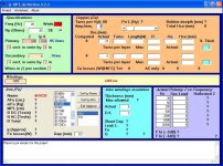
You can find equations anywhere.
For the most part they are used inside that :
http://www.dissident-audio.com/OPT_da/Page.html
Just a tool that helps putting pieces together.
Yves.
lt cdr data said:Bonjour Yves.
I can't seem to install that program, any ideas?
Damned ! That is the worst that could occur

Where does it stop ? wich message ? if any !
Of course, you browsed the readmefirst file 😀
Try to tell me more.
Yves.
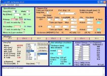
Hi mayky,
You must change the "default" decimal separator in your WINDOWS regional options.
To do that, open the Windows configuration panel, then choose Regional Options, date , time (or so).
Then choose "Change numbers format" and "Personalize"
On the first rolldown box, replace the comma"," by a dot".".
Then close all intermediate windows with OK button.
Should work !
Yves.
Hi mayky,
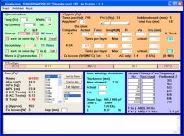
If you allow me to make some remarks !
I beleive your design can be improved largely.
I assumed that th gap is fixed by construction as usual with this kind of laminations.
For this first reason, you must accept to increase the lowest frequency to 25Hz for the same power to keep induction at reasonable value.
The major drawbackis the AC losses which should not be higher than, says, 10%.
So, I've increased the primary wire diameter to 0,4mm.
I've adjusted the primary L (in fact, global turns) to balance AC and DC induction.
Similary, the secondaries are far from optimized: You could put 118 turns per layer with the wire you choosen, but you only use 23 !
Prefer paralleled secondaries and search a combinaison of wire diameter wich use more efficiently the available copper space.
Now, you need 81 turns per section while you have room for 84. Well filled and fits in a single layer.
This also reduces leak L because it is somewhat proportional to the total thickness of the full winding.
Looking to interleaving, much better results are obtainable using "split" extreme sections.
And less sections means an easier to wind unit.
See attached suggestion but you may have other limitations not know by me !
Yves.
Attachments
hi yves, still can't get it to install.
I get to the part, after I run setup.exe,
where I try to install by pressing the button, and it says l'installation....et reussi.
I seem to have the decimals with a dot.
any ideas? merci beaucoup
I get to the part, after I run setup.exe,
where I try to install by pressing the button, and it says l'installation....et reussi.
I seem to have the decimals with a dot.
any ideas? merci beaucoup
http://www.delevan.com/help_center/techlibrary/formulae.html
http://www.tortech.com.au/toranalysis.html
http://ludens.cl/Electron/Magnet.html
http://www.consult-cpr.com/Additional Pages/Eng LinksB6.html
http://users.catchnet.com.au/~rjandusimports/formula_1.html
http://www.ee.surrey.ac.uk/Workshop/advice/coils/terms.html
http://www.ee.surrey.ac.uk/Workshop/advice/coils/index.html
http://en.wikipedia.org/wiki/Transformer_design
http://www.bcae1.com/trnsfrmr.htm
lt cdr data said:hi yves, still can't get it to install.
I get to the part, after I run setup.exe,
where I try to install by pressing the button, and it says l'installation....et reussi.
I seem to have the decimals with a dot.
any ideas? merci beaucoup
So, installation prog says "succesfully installed" ! !
May be the .exe file is somewhere ?
Check with "install / remove" Windows utility.
Somewhere in installation process, you can specify where you want put it.
It must be in the folder where files where decompacted.
If it is, what happens when launching ?
Yves.
aha, yes its there!!
merci beaucoup,
what happened is that it wasn't listed on my windows menu for programs,
but it is in C drive, program files.
strange
I left it as the default name and install location.
anyway, thanks and will have a play over the next few days🙂
merci beaucoup,
what happened is that it wasn't listed on my windows menu for programs,
but it is in C drive, program files.
strange
I left it as the default name and install location.
anyway, thanks and will have a play over the next few days🙂
- Status
- Not open for further replies.
- Home
- Amplifiers
- Tubes / Valves
- online transformer info for newbies