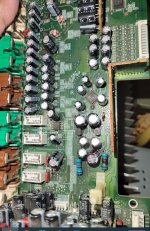
Hello,
I have a Onkyo tx-sr805 that is powering on but the audio output is low regardless of the volume.
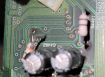
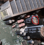
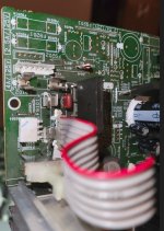
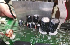
Upon inspection, I found some bulging caps, and 2 burnt resistors on pre-amp board that had melted and no longer soldered on the board.
Given the amount of heat these amps generate, i figured that the over years these voltage rails resistors were damaged by heat.
Replaced the capacitors and the resistors, matched the resistance for R4001/R4002 22ohm but increased wattage to better handle the heat.
Reassembled the unit and turned the power on, only to witness the resistors smoke and burn out right away.
so, i would imagine, this means, there is a short somewhere. Hoping the experts can suggest which parts could be suspect since nothing else looks visually bad.
The pre-amp board takes power from the speaker output board, i checked the input voltage reaching the pre-amp board and confirmed that i am getting +-15V so appears that the input voltage is good.
Frank
Attachments
R4401/4402 are fuseable resistors designed to fail when a problem arrises. Never fit the wrong type of component in these places or you are asking for trouble.
Find your fault and fit the correct resistors, (22R 1/2W MO).
Check any capacitors have bee fitted the correct way around!
That 2k2uF cap looks very over worked. Component numbers may help engineers from guessing.
Find your fault and fit the correct resistors, (22R 1/2W MO).
Check any capacitors have bee fitted the correct way around!
That 2k2uF cap looks very over worked. Component numbers may help engineers from guessing.
Without R4401 and R4402 in place, are the +/- 14.4 rails ok?
If yes, it's the +/-8.5V regulator circuit or something on those rails.
22 ohm 1/2W can handle 150mA.
If you hav a dual power supply, have the R4401/4402 resistors removed and connect it to the C4401/4402 nodes.
Slowly turn up the (tandem) voltage and notice the current. Stop if it starts to exceed that 150mA.
Can you post a picture of the load of the +/-8.5V regulators?
Hello,
Thank you for the quick replies, please know that I am not an expert, so bear with my silly questions.
JonSnell Electronic: Thank you for explaining the resistors purpose, I clearly made a mistake in replacing them with larger wattage, my early rationale was that the old ones burnt out over a decade of use, not due to a short. Clearly, I was wrong, ordered the correct ones just now. Also, the photos you see are prior to recapping any capacitor that looked bad. I made sure the polarity was correct when replacing them.
Citizen124032: I did not test that; I disconnected the power connector to the preamp board and measured the voltage via multi-meter on the connector and confirmed that I was sending 15 volts on both +-. I did not check amperage will do that and let you know, fyi, I do not have an external PSU or an oscilloscope, just a basic digital multimeter. Also these onkyo's sandwich the boards badly, so the preamp board once installed is hard to reach and when removed to work on has no power to it. What would i need to do to test the +-8.5v regulator circuit? Should I order and replace the transistors to rule them out?
Service manuals:
https://elektrotanya.com/onkyo_tx-sa805_sr805_sm.pdf/download.html
https://www.hifiengine.com/manual_library/onkyo/tx-sr805.shtml
Measure the voltage over the 22 ohm resistors (as timing permits). It is the regulator for the volume control.What would i need to do to test the +-8.5v regulator circuit?
Inspect the board for shortings / contaminations.
If the 15 regulators are ok, leave it as is.
Attachments
Thank you will check over the weekend. Makes sense that the volume is impacted as the audio output was constantly low on all output channels, even though the digital volume would display the correct db.
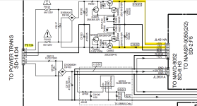
I did attempt to check the current on the +15v and -15v JL4014A output, which is received on the pre-amp board via JL4014B, while the voltage reading are still ok, on the amperage my multimeter has 10A and then 200ma settings. when set to 10A i get nothing and setting to 200ma, shows that the current is exceeding that amount, unplugging AC power, i do see numbers start from 200ma and slowly decrease as the capacitors discharge.
You had mentioned that the 22ohm 1/2 watt resistors can handle 150ma, makes me wonder if the current is exceeding. Unfortunately, the multi meter does not have too many options so track down the exact current.
The 10A setting on your mm has a separate bus to connect your lead to (I guess).
200mA is to much. I suspect a short at that volume board.
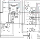
Check caps 4413 & 4415!
200mA is to much. I suspect a short at that volume board.
Check caps 4413 & 4415!
Thank you Citizen, until you mentioned the 10a lead, i did not notice that there was a 10amp option to wire the +ve lead on the multimeter. I did that and started to measure the amperage, was getting some very high numbers and then, i suspect that with the tiny wires on JL4014A connector, i may have touched both the +ve and -ve 15volt outputs as there was a spark , some smoke and both the 125v 4amp fuses blew.😢
I will pick up the fuses tomorrow, but I suspect that if the regulators were not shorted earlier, they are likely by now., Smoke could not have come from the fuses.
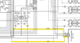
Also, I do want to clarify on thing, my amp/volt measurements being taken were from the JL4014A unplugged on the board that takes in the transformer output to inverters/regulators and then sends it the +15v, -15, GND and 12V to the pre-amp board where the resisters are burning out., as this circuit is on the speaker output board, this tells me that the high current problem is on this board and not on the pre-amp board.
With that, caps 4413 & 4415 look healthy visually on the preamp board. I can desolder them and check for short.
See pictures attached for illustration. You will see the higher wattage resistors that i had installed with the R4401 burnt which is on the +15V rail. That leads me to further suspect that a component pr more along the +15v rail are having issues.
I can remove all the transistors, resistors and capacitors and test each one, though not sure how much testing can happen with a basic multimeter.
Frank
Attachments
No worries, i found a speaker output pcb board for this receiver on eBay. hoping that it is a healthy board, and I can swap and test voltage and amperage measurements in a week or so when the board arrives.
Replacement board arrived today, swapped it and put new correct matching 22ohm 1/2 watt resistors R4401/R4402 on the preamp board . gave power and R4402 smoked right away.
The odds of the new ebay board being blown would be low, so we are back to what is causing R4402 to burn up as soon as the unit gets standby power.
I pulled out Q4401(A950) and Q4402 (C2120) and measured Hfe, C2120 is npn and hfe was 246, a950 is pnp and measured 368. little i could google on datashseets, value seems to be in range.
r4403, r4404, r4405 and r4006 are all reporting correct resistance.
any other suspects, none of the caps appear to be shorted on the premp board that I can tell.
One more thing, likely not an isuue but calling it out just in case.
I just realized that the original burnt resistors were metal oxide and the replacement ones are metal film, could it be that they are unable to tolerate the power surge during turn up and therefore burning up? Should I order metal oxide and try them?
Frank
I just realized that the original burnt resistors were metal oxide and the replacement ones are metal film, could it be that they are unable to tolerate the power surge during turn up and therefore burning up? Should I order metal oxide and try them?
Frank
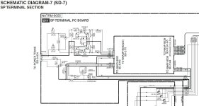
it helps if you refer to the schematic page in the service manual where the fault is happening, in this case it's p17/308, and you expect someone to go through 308 pages to find the place and help you troubleshoot? 🙂 really now
The +/-8.5V regulators only power the Q4405 (CS3318) so there is your idea to work with. You need to figure out what's drawing too much I and burning the resistors R4401,4402, helps if you get them right too
The +/-8.5V regulators only power the Q4405 (CS3318) so there is your idea to work with. You need to figure out what's drawing too much I and burning the resistors R4401,4402, helps if you get them right too
Thank you rsavas. Apologies as I am not a electronics expert and also new to asking questions in forums for help. Will take the feedback and improve upon.
When you say I need to get the resistors R4401 and R4402 right, do you mean that I need to order metal oxide resistors and that metal film are the wrong ones.
Also, not sure if you had seen my response above on some of the testing I have done on +/- 8.5 voltage regulator components, some of them are SMD which I unfortunately do not have the tools or skills to remove and test them.
Frank
I meant that you did not reference those resistors correctly in the first post, no corrections and also assume that you can put any type of resistor in there as a substitute which is incorrect.
Sounds to me like it’s beyond your capability to troubleshoot and service a complex design like this one. Probably beyond many others as well so it’s just something left to experts if you can find one. Did you ask the manufacturer if they still support servicing on this device?
Sounds to me like it’s beyond your capability to troubleshoot and service a complex design like this one. Probably beyond many others as well so it’s just something left to experts if you can find one. Did you ask the manufacturer if they still support servicing on this device?
- Home
- Amplifiers
- Solid State
- Onkyo TX-SR805 pre amp board failure
