Hello, I have been trying to repair the watt/power Meters on an Onkyo M-508.
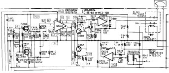
The driver circuit is identical to the M-504 (see attached schematic), which there has been a few threads on, eg. https://www.diyaudio.com/forums/solid-state/328277-onkyo-m504-meter-malfunction.html.
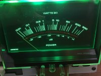
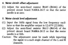
The problem is, that the meters only give very little/low response: When I feed in a 1 Khz test signal corresponding to 12,65 V output, it should be possible to calibrate the Meters to 0db. But they only go up to about -40db.
Both meters do move though (and in a similar manner), and they both have the correct DC resistance out of circuit. So the fault seems to be in the rather complicated driver circuit.
When I first started fault finding, both Q601 and Q602 were dead. The originals are SK246, which I couldn't get, so I have replaced them with SK117.
Q604 and Q605 are also new, same type as original.
I have also replaced the main driver chip Q603 (TA7318P). I first tried ordering the new devices from China, but those didn't work at all. Clone/fake chips with different pinout maybe? But I finally got hold of a new original Toshiba from England.
I have also tried replacing the opamps, but that didn't help.
So the status is now:
Power supply and rail voltages are all good:
+/- 21V on the opamps, and 17V for the TA7318P.
All the check voltages given on the schematic are also correct (or very near), except the Bases of Q604 and Q605, were I have 0,65V instead of the -3.8V shown (!)
For the Left channel, I can follow the 1 Khz test signal from input, to the Gate of Q601 (3,1VAC), and on through the TA7318P, but then the signal seems to "disappear" after the trimpot R615!
I have had the trimmer out and checked that it works and measure correctly, and the 601 relay works fine (has continuity when closed).
So something appears to be attenuating the signal somewhere between the TA7318 and the Meters, but I can't for the life of me figure it out 😕
Logically, it must be a common point or component for L and R, as both Meters have the exact same issue. Might just be a "stupid little detail", since the Meters do move some, and the Meter trim pots work, and I can see that the meters have a dependency (as they should).
I would greatly appreciate your help, since I am all out of ideas..
Thanks!
The driver circuit is identical to the M-504 (see attached schematic), which there has been a few threads on, eg. https://www.diyaudio.com/forums/solid-state/328277-onkyo-m504-meter-malfunction.html.
The problem is, that the meters only give very little/low response: When I feed in a 1 Khz test signal corresponding to 12,65 V output, it should be possible to calibrate the Meters to 0db. But they only go up to about -40db.
Both meters do move though (and in a similar manner), and they both have the correct DC resistance out of circuit. So the fault seems to be in the rather complicated driver circuit.
When I first started fault finding, both Q601 and Q602 were dead. The originals are SK246, which I couldn't get, so I have replaced them with SK117.
Q604 and Q605 are also new, same type as original.
I have also replaced the main driver chip Q603 (TA7318P). I first tried ordering the new devices from China, but those didn't work at all. Clone/fake chips with different pinout maybe? But I finally got hold of a new original Toshiba from England.
I have also tried replacing the opamps, but that didn't help.
So the status is now:
Power supply and rail voltages are all good:
+/- 21V on the opamps, and 17V for the TA7318P.
All the check voltages given on the schematic are also correct (or very near), except the Bases of Q604 and Q605, were I have 0,65V instead of the -3.8V shown (!)
For the Left channel, I can follow the 1 Khz test signal from input, to the Gate of Q601 (3,1VAC), and on through the TA7318P, but then the signal seems to "disappear" after the trimpot R615!
I have had the trimmer out and checked that it works and measure correctly, and the 601 relay works fine (has continuity when closed).
So something appears to be attenuating the signal somewhere between the TA7318 and the Meters, but I can't for the life of me figure it out 😕
Logically, it must be a common point or component for L and R, as both Meters have the exact same issue. Might just be a "stupid little detail", since the Meters do move some, and the Meter trim pots work, and I can see that the meters have a dependency (as they should).
I would greatly appreciate your help, since I am all out of ideas..
Thanks!
Attachments
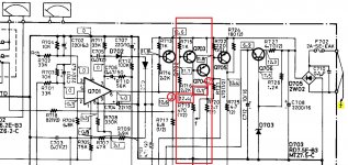
The problem has to be wherever connection "f" goes after R647. Q604 and 605 are now being fully turned on and draining away all the signal.
Very good suggestion, thanks! The "f" seems to lead over to a rectifier and a fuse - see right hand side of the attached picture.
I rather hope one of these are defective, that would be a nice simple solution - I will check it, and see what I find..
I rather hope one of these are defective, that would be a nice simple solution - I will check it, and see what I find..
Attachments
Hi Craig, yes you are correct!
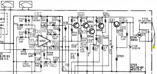
The base of Q604 and Q605 is connected to the Collector of Q704 through R647.
I have attached the complete main schematic in two parts, extracted from the Service manual.
The other "f" that I first spotted, is just connected to the AC secondaries from the transformer, and has no connection to Q604/Q605.
On the Collector of Q704 the schematic lists 0.1V, but I have 12.8V there! - So that explains why the Q604/605 are fully on.
But after working on the problem for the last couple of hours, I still can't figure out WHY Q704 is turned on and has 12.8V on the Collector:
As far as I can see, Q704 is controlled by Q703, which in turn is controlled by pin 6 of the Q701 IC. There should be 1.0v on this Pin 6 and I have 0.9V, so pretty close.
I have measured all resistors in the area, and they were all good. I have had all the nearby transistors (Q 702, 703, 704, 705, 706) out for testing (twice!) - and now I have replaced Q703, 704 and 705, just to try something and rule out a leaky transistor. But that didn't help any.
One other thing: The Meter bulbs have been replaced with LEDs, which has much lower current draw. The incandescent bulbs draw about 2w each. I wonder if that could be a factor here, since the power supply for the "outer" bulbs are coming from Q704 via R720, a large 2.7 ohm resistor?
It seems these bulbs should be Off when the Meters are On, and vice-versa. But when the Meters are On, there is actually still around 8V going to the outer sets of bulbs.
To test this "theory", I tried connecting 100r resistors in parallel with the LEDs, and while that did draw down the voltage slightly, it didn't solve the problem with the Meters.
Perhaps I should also have a closer look at the Meter on/off switch S701, in case it doesn't make a good "On" connection? (although it has been cleaned quite well).
Attachments
If your amp's speaker relay contacted when turned on, you can check the voltage one by one, if point 1 voltage is not around 12.4V, then Q703 or R719 maybe open, next to point 2, if voltage not close to 0.1V (must below 0.6V), then Q704 maybe open
For the open circuit place, you need to check PCB connections or parts broken and need replacement
For the open circuit place, you need to check PCB connections or parts broken and need replacement
Attachments
Last edited:
The way I see it, the METER switch just connects Q705 base to +12.6 V via R723 when turned OFF. This in turn makes Q705 stop supplying the "inner" bulbs.One other thing: The Meter bulbs have been replaced with LEDs, which has much lower current draw. The incandescent bulbs draw about 2w each. I wonder if that could be a factor here, since the power supply for the "outer" bulbs are coming from Q704 via R720, a large 2.7 ohm resistor?
It seems these bulbs should be Off when the Meters are On, and vice-versa. But when the Meters are On, there is actually still around 8V going to the outer sets of bulbs.
The "outer" bulbs would then have to be the ones associated with protection.
I looked up the TA7317P datasheet, and pin 6 on Q701 is the relay driver pull-down to ground (pin 4). So when everything is fine and dandy, Q702 would be on, enabling meter relay RL601 (is it?), and so would be Q703, turning off Q704 along with the "outer" bulbs.
Please check voltages at Q703. I suspect you may have a bad trace or pad either in the +12.6 V supply or around Q703, so it is unable to pull up Q704 base against 470 ohm R719. Some continuity / resistance checking may be advised. A weak +12.6 V may also explain worse than usual contact in RL601 (maybe check coil voltage if you can get there).
Speaking of conrinuity, make sure local ground at the relevant places agrees with ground elsewhere.
I don't see how reduced bulb current draw would be a problem, it basically just makes the other parts' life easier here.
Last edited:
Hi, yes the outer bulbs are related to protection circuit, and they switch off a few seconds after the amp is turned on (when all is well).
The 12.6V rail is actually around 14.5V when the Meter bulbs are disconnected, and with LED bulbs, it only drops slightly. So the 12.6V rail is certainly strong enough.
With the bulbs disconnected, Q703 has 13.6V on the Base, and Q704 is well turned on, with about 13.6V on the Collector (which should now be 0.1V)
I will admit I only "kind of/almost" understand the whole Meter driver circuit and how it interacts with the bulbs, protection etc, but it seemed to me that the current draw of the bulbs had to be significant.
So I went back, and again tried connecting some power resistors to partially simulate the current draw of the bulbs. I think perhaps the first time I did this, I only connected resistors after Q705, which feeds the main bulbs that stay on. But now I also did it on Q704, and what happened?... IT WORKED!
With a 100 ohm resistor to draw some current from Q704 (through R720), everything came good, and I now get a negative voltage on the bases of Q604/Q605 (like it should be), and the Meters works perfectly! No problems!
Also, now the outer "warm up lights" actually switch off completely, instead of just dimming a bit.
"Even blind chickens find a corn once in a while" 🙄
Without understanding it completely, I can only conclude that the resistance of the incandescent bulbs (when off) are designed into the circuit, and without this it just doesn't work.
So... now what?
I have two ideas:
1. Put resistors in parallel with the LEDs. This is simple, and will work just fine (it seems), but not so elegant..
2. Modify the circuit so it works with LEDs, and without big power resistors stuck on there. This would be the best solution I think, but not sure exactly what values or components to change. Will have another look tomorrow, and see if I can figure it out..
Thanks for your help, I appreciate it 🙂
Huh. What do you know.
Re: 2), I imagine that increasing the value of R719 should make it easier to turn off Q704. I'd say try a 2.2k and see how well that works.
R719 is quite low so that more than enough base current (~25 mA) is provided to Q704 so it will go deeply into saturation while driving the 600 mA (probably somewhat less) lamp load.
If you know the LED current draw, you could consult the beta(Ic) graph in the 2SK772 datasheet to get an estimate for the ratio of old and new base current, and resize the resistor accordingly.
Last edited:
Success!
So I can definitely confirm, that the M-504/M-508 Meter driver circuit only functions correctly with incandescent bulbs for the Meter lighting!
It is the "protection" bulbs (in the outer positions) that are critical for the actual Meter function.
Instead of fiddling with parallel resistors and modifying the circuit, I decided to simply revert to using the original bulbs for the red protection light.
That solved the problem, and voltage check points are now just like the schematic specifies: 0.1V on the collector of Q704 and -3.8V on the bases of Q604/605.
I did first try increasing value R719 as suggested by sgrossklass, but even with a 2M, a 100r was still needed in parallel with the LEDs for the Meters to switch on.
LEDs does work as replacement for the inner bulbs (the main lighting), but the light will then no longer switch off, when turning the Meters off (there is a button for that). Instead the LEDs just go dim. But this doesn't influence the actual function of the Meters. This can (again) be "fixed" with a 100r parallel to the LEDs - then they can be switched off completely. But I quite like that a dim green light stays lit in the Meters, so I will leave it as is..
I don't fully get how the circuit works, but it must be due the bulbs cold DC resistance, which is around 10 ohm - with 4 in parallel, that is a 2.5 ohm resistor to ground, when no current is flowing. I guess that provides a way to pull down the "ghost" voltage on the collector of Q704, allowing the Meters to activate. Of course, when the bulbs can draw current, the resistance rapidly rises to about 90-100 ohm, drawing about 150mA each.
But a peculiar design really, because if all the Protection bulbs are burned out/dead, then the Meters also will stop working. Perhaps that rarely happens in real life, but good to know.
Attachments
Last edited:
- Home
- Amplifiers
- Solid State
- Onkyo M-508 Meter circuit problems