hi all,
i got this onkyo amp recently and the left channel in it was not working. (It just gives a deep bass sound and goes in to protect mode) The right channel's working fine. It has mn2488/mp1620 transistor pair for the amp and it has few other small transistor before it goes in to the mn1620/mp1620.
I measured the resistance across the emitter/collector in them and all of them show open circuits(for both Rch and Lch). So i'm guessing they are ok. But when i mesure voltage across the same pins, right ch trans. stay contant at 57v but in the left ch. one of them is at 47 and the other is at 70v.
So does this mean that the left trans. pair is blown or could it be some other problem. (there are 3 more transistors between the preamp input and main transistor input, i chekd them for resistance but they seem to be ok as well.
hope im making sense🙂. Juz wanna figure out if its the mn1620/mp2488 that has the problem or not. also is there anything else i cud measre to check.
thanks for any help...:>
Hi dmx2020,
There is not enough information to give you an answer, but I'll bet there are some other problems. An output device failure will mean heavy current flow unless the emitter resistors are open - and some others as well.
-Chris
There is not enough information to give you an answer, but I'll bet there are some other problems. An output device failure will mean heavy current flow unless the emitter resistors are open - and some others as well.
-Chris
As a start the type# could bring some help as well as a schematic.
Also, do you have experience with troubleshooting/repair?
In case you haven’t: beware of the Big power supply capacitors.
Discharge before measuring.
/Hugo 🙂
Also, do you have experience with troubleshooting/repair?
In case you haven’t: beware of the Big power supply capacitors.
Discharge before measuring.
/Hugo 🙂
Hey Hugo,
Everyone should have a handtool with a chunk missing! Of course, Hugo is correct. THere are many gotcha's in servicing since electricity is invisable. You can feel it and it can kill you.
-Chris
Everyone should have a handtool with a chunk missing!
Of course, Hugo is correct. THere are many gotcha's in servicing since electricity is invisable. You can feel it and it can kill you.-Chris
I'm still recovering from a discharging cap who hit me good two days ago despite many years of experience and one moment of carelessness. Hence my post. 🙂
/Hugo
/Hugo
Yeah, I still get nailed from time to time. Then it bugs me how stupid I was. Most of the damage can come from jerking your arm back (involuntary reaction). So you still have the jitters?
It's easy to take these things for granted.
It's easy to take these things for granted.
Apart from a burned finger, all seems back to normal.
320VDC from a TV primary is quite a lot, luckily I had the one-hand-in-the-pocket.
Meanwhile we're going off topic but... the thread stays on top. 😀
/Hugo
320VDC from a TV primary is quite a lot, luckily I had the one-hand-in-the-pocket.
Meanwhile we're going off topic but... the thread stays on top. 😀
/Hugo
thanx 4 the advice guys,
The model number's onkyo TX866 discrete amp tuner.
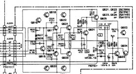
I have attached a schematic of the Left channel of the amp pcb( its the same for the right ch).
On it u can see the peramp input coming in from the left side, and then it goes to the 3 transistors i was talkin about(Q515, Q517, Q519). And then it goes to the big power transistors( Q521, Q523).(These are the MN2488/MP1620 pair) In btween these 2 pnp/npn combination the output comes to the speaker(L out)
Im not sure what all the other transistors are for(Q601-Q605) but i think they are 4 the protection circuit.
The power comes in from +B1 and -B1 of JL504 and its at about 100v.
As i said above, at coll/emmiter of Q521 is around 70v and Q523 is at around 47v whereas on the right side they are both at about 57v.
I'm sure this time its a lot clearer, so is there a way to check if the fault is with Q521/523 or any of the other transistors.
The part numbers are:
Q515: 2sc1740 (npn)
Q517: 2sd1763 (npn)
Q519: 2sb1186 (pnp)
and mn2488/mp1620 are the Q521/Q523.
Hpoe this is enuf info. Thnx in advance...
The model number's onkyo TX866 discrete amp tuner.
I have attached a schematic of the Left channel of the amp pcb( its the same for the right ch).
On it u can see the peramp input coming in from the left side, and then it goes to the 3 transistors i was talkin about(Q515, Q517, Q519). And then it goes to the big power transistors( Q521, Q523).(These are the MN2488/MP1620 pair) In btween these 2 pnp/npn combination the output comes to the speaker(L out)
Im not sure what all the other transistors are for(Q601-Q605) but i think they are 4 the protection circuit.
The power comes in from +B1 and -B1 of JL504 and its at about 100v.
As i said above, at coll/emmiter of Q521 is around 70v and Q523 is at around 47v whereas on the right side they are both at about 57v.
I'm sure this time its a lot clearer, so is there a way to check if the fault is with Q521/523 or any of the other transistors.
The part numbers are:
Q515: 2sc1740 (npn)
Q517: 2sd1763 (npn)
Q519: 2sb1186 (pnp)
and mn2488/mp1620 are the Q521/Q523.
Hpoe this is enuf info. Thnx in advance...
Attachments
As far as I can see all the Q6xx are protection circuit and a link to the Rch.
Taking out the 5 Q5xx transistors is probably easy to do for measuring. Have a look at R537 and 539 as well as the emitter R's.
/Hugo 🙂
Taking out the 5 Q5xx transistors is probably easy to do for measuring. Have a look at R537 and 539 as well as the emitter R's.
/Hugo 🙂
Hi dmx2020,
I think we need to see the voltage amp section as well. It sounds like you have a problem further up. The outputs in there belong in a Sony. I suspect it has been serviced before. The original #'s are on your schematic.
-Chris
I think we need to see the voltage amp section as well. It sounds like you have a problem further up. The outputs in there belong in a Sony. I suspect it has been serviced before. The original #'s are on your schematic.
-Chris
Chris is right, these devices are darlington made for Sony by Sanken. The Sanken parts are $4 each and the sony subs are $26 each ;-).
yea, it looks like it has been serviced before and someone has has replaced all Q521-Q524 on both channels with the sony ones. So do u think it makes difference in sound output power. (its originally rated at 70w/ch)
For chris, do u mean that there might be a problem in the power supply(B+ & B-). (i hope thats what u meant by voltage amp section) Well i measured Lch and Rch B-,B+ and they are both the same (at 100v). Pl. let me kno what u think.
To hugo, do u have to take them out for measuring, If they show a open circuit while in the circuit does that still count? and if they pass the emitter R's does that confirm that they are ok?
i checked the preamp input to both channels with a speaker they are also fine.
If u guys need anymore schematics juz let me kno, and thanx for all the help so far.
We need the part of the schematic before JL504.
Taking the transistors out of circuit is the only way to know for sure if they are good or bad.
/Hugo 🙂
Taking the transistors out of circuit is the only way to know for sure if they are good or bad.
/Hugo 🙂
hi hugo,
i have uploaded a whole schematic of the amp section which includes the bit before jl504. Pl. let me kno ur email address if u need a higher resolution version cuz i can only upload up to 100kb.
regards
dmx
i have uploaded a whole schematic of the amp section which includes the bit before jl504. Pl. let me kno ur email address if u need a higher resolution version cuz i can only upload up to 100kb.
regards
dmx
Thank you, schematic looks good enough I think.
Anyway, we need to know how the five transistors and surrounding resistors measure before proceeding.
In case you don't know exactly how to measure, here's a good link. To give you a bit more work, you could also compare your measurements with the out-of-circuit transistors from the good channel.
/Hugo 🙂
Hi dmx2020,
I meant there is a problem in the voltage amplifier stage, your raw power supplies are okay. When testing, do not swap good parts to the bad side. That's a good way to end up with two bad channels.
Look at the 220uF / 16V capacitor and the voltages around Q501/502. The two base voltages should be the same within a couple mV. Also check the solder joints in that area.
-Chris
thanx for the link, hugo. thats gonna come in real handy.
i'll get back to u guys tommorrow on how the measurements of the 5 Q's and the voltage amplifier stage went.
thanks for all the the help so far.
dmx.
i'll get back to u guys tommorrow on how the measurements of the 5 Q's and the voltage amplifier stage went.
thanks for all the the help so far.
dmx.
hi again guys,
i measured the 5 transistors on the amp pcb and they all turned out to be ok. Only the resistor R539 was burnt but R537 and R541 were ok.
From the voltage amp, at the 2 bases of Q502 (for the right channel) the 2 voltages were equal at 100mV, but for the left ch (Q501) one was at 200mV and the other was at 4V.
Later i found Q511 PNP and R529 was bad. All the other resistors in the Vamp were ok so i assumed that the transistors on them were also ok.
So do u guys think if i change Q511 and the 2 resistors it'll be ok or is there somthing else that should also be looked at before turning the power on.
Thanx in advance
dmx.
I would lift the collectors of Q511/513 and power up the amp with a variac if you have one.
In case you haven't, use a light bulb of about 60W in series with the mains to avoid excessive current. Be careful with the connections you make here. If all looks normal at both collectors you could assume all is fine for the premiere.
/Hugo 🙂
In case you haven't, use a light bulb of about 60W in series with the mains to avoid excessive current. Be careful with the connections you make here. If all looks normal at both collectors you could assume all is fine for the premiere.
/Hugo 🙂
- Status
- Not open for further replies.
- Home
- Amplifiers
- Solid State
- ONKYO amp trans. problem