Fantastic!!!! 😀 😀 😀 😀
Keep at it, the 2nd board will go much faster, as you now know how to make a successful channel.
Keep at it, the 2nd board will go much faster, as you now know how to make a successful channel.
How long does it take for things to stabilize? Wondering how long I should wait to re-bias/set offset and check temperature of the heat sinks.
An hour should be enough. BTW, how hot are the heatsinks? How many seconds can you hold you had on them. (And what's your bias?)
I only ran it for about 10 minutes at ~450mv before I had to leave for dinner. In that time, it warmed up a little but not nearly enough that I had to remove my hand at all.
I'll bias it up to 500mV tonight when I work on the second channel and let it run for a while using the hand method to monitor temperature along the way.
I'll bias it up to 500mV tonight when I work on the second channel and let it run for a while using the hand method to monitor temperature along the way.
Yes, that's correct. Used my handy dandy Hakko desoldering pump (a Godsend) to remove the old ones in short order and used the 6.8k ones I had in my ever growing stash of spare parts.
Well done!
Did you make R3 and R4 6.8k instead of 2.2k?
Woohoo!!!
After a few minor trip ups, all is well in the world.
First, I had problems again with the whole bulb tester thing. But this time, I couldn't get out of it even after experimenting with the pots. (Not sure why that worked last time in the first place, but whatever.) But then I noticed that the bulb would dim when I removed the oscilloscope leads. (The DMM measurements were fine.) AND, it would happen after I only attached the ground wire of the oscilloscope. So... I ended up just using DMMs and got past the bulb thing. Not sure why I didn't have that problem with the other channel.
In any case, second, I couldn't get the bias high enough similar to the other channel so I got the handy dandy Hakko out but this time, I lifted a pad. Doh! Problem was that I couldn't maneuver the Hakko so that it was perpendicular to the PCB since I didn't leave enough slack in the wires to create room. After a few moments of panic (I've never lifted a pad before) I managed to get the new 6.8K resistor soldered in despite the lifted pad. As you might expect, I was more careful with the other resistor and that one went off without a hitch.
Then the rest went easy as pie. Biased up to about 520mV with zero offset. Checked the other side and tweaked it to the same settings. Plugged in my cheapo test speakers and it was like angels singing from heaven. 😀
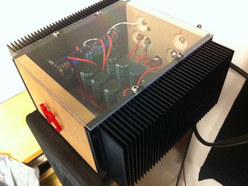
Then I got to work on the drilling some holes for the letters. Added a couple rubber feet to the top so there's a small gap for ventilation. Snapped a few pictures. Plugged in my Zaph ZDT 3.5 speakers and listened while I cleaned.
As far as heat, I can keep my hands on the sinks indefinitely. They definitely get warm, but not painfully so. It helps that the room is pretty chilly at about 65 degrees. Also, the open bottom and aluminum bottom panels likely help a little. And finally, I haven't biased up to 600 mV yet so I'll see if the temp changes significantly once that happens.
Sound-wise, I didn't do any critical listening as you can tell from the photos so no judgments yet. (All I did was plug my iPhone in.) But from the little I heard, I think I'll be very happy with the amp. I may do some side by side listening with my chip-amp too just for fun.
Thanks again for everyone's help and interest in my build. Hopefully some other folks will have learned from my mistakes and questions.
As they say, this post is nothing without pictures, so without further ado:


After a few minor trip ups, all is well in the world.
First, I had problems again with the whole bulb tester thing. But this time, I couldn't get out of it even after experimenting with the pots. (Not sure why that worked last time in the first place, but whatever.) But then I noticed that the bulb would dim when I removed the oscilloscope leads. (The DMM measurements were fine.) AND, it would happen after I only attached the ground wire of the oscilloscope. So... I ended up just using DMMs and got past the bulb thing. Not sure why I didn't have that problem with the other channel.
In any case, second, I couldn't get the bias high enough similar to the other channel so I got the handy dandy Hakko out but this time, I lifted a pad. Doh! Problem was that I couldn't maneuver the Hakko so that it was perpendicular to the PCB since I didn't leave enough slack in the wires to create room. After a few moments of panic (I've never lifted a pad before) I managed to get the new 6.8K resistor soldered in despite the lifted pad. As you might expect, I was more careful with the other resistor and that one went off without a hitch.
Then the rest went easy as pie. Biased up to about 520mV with zero offset. Checked the other side and tweaked it to the same settings. Plugged in my cheapo test speakers and it was like angels singing from heaven. 😀
Then I got to work on the drilling some holes for the letters. Added a couple rubber feet to the top so there's a small gap for ventilation. Snapped a few pictures. Plugged in my Zaph ZDT 3.5 speakers and listened while I cleaned.
As far as heat, I can keep my hands on the sinks indefinitely. They definitely get warm, but not painfully so. It helps that the room is pretty chilly at about 65 degrees. Also, the open bottom and aluminum bottom panels likely help a little. And finally, I haven't biased up to 600 mV yet so I'll see if the temp changes significantly once that happens.
Sound-wise, I didn't do any critical listening as you can tell from the photos so no judgments yet. (All I did was plug my iPhone in.) But from the little I heard, I think I'll be very happy with the amp. I may do some side by side listening with my chip-amp too just for fun.
Thanks again for everyone's help and interest in my build. Hopefully some other folks will have learned from my mistakes and questions.
As they say, this post is nothing without pictures, so without further ado:
 I like it tanks for posting
Wow! Looks great! The red letters look very sharp. 🙂
What are the speakers? (edit - You said it in your post, they are Zaph ZDT 3.5)
What are the speakers? (edit - You said it in your post, they are Zaph ZDT 3.5)
Wow, who needs more than a few watts? I'm driving the F5 with my laptop and amb gamma 1 DAC (1.6VRMS) via USB and it gets more than loud enough at less than 1/3 volume! My speakers are about 4ohms nominal and reasonably sensitive so I was expecting to be toward the upper range of my volume rather than the bottom. So pleasantly surprised.
What does this statement mean?...........at less than 1/3 volume............
What does this statement mean?
I'm guessing that's at 1/3rd of the maximum volume range allowed by his playback software/OS?
Or perhaps a psychological point where it feels like he has lots of room on the knob to turn it up... As opposed to having to turn the knob towards the end of it's travel. It's more important than one thinks.
Regardless, it's an interface position, instead of a measured output.
Regardless, it's an interface position, instead of a measured output.
Yes, that's right. I guess I can measure the output on my scope to see what that translates into rms and peak-wise. Will do that tonight.
I'm guessing that's at 1/3rd of the maximum volume range allowed by his playback software/OS?
Just for the record, I'm getting 54mV ripple after the first pair of caps in the PSU box. After the PSU PCB, I get 14mV. (got my new to me fluke 45 DMM today which is why I can measure that now.)
Really? Will I be able to hear the difference? To be honest, I have no idea how good/bad 14mV is in the grand scheme of things and I feel like my speakers are already pretty good. Or at least, I'm not sure how much better my speakers will ever get!
- Status
- Not open for further replies.
- Home
- Amplifiers
- Pass Labs
- oneplustwo F5 build thread