Hmm... well, the two MOSFETs on this channel both read 45. And both on the other channel read open. So where does that leave me? 😕
BTW, thanks to everyone for all the help! Hopefully I'll have something to show for all your input shortly.
BTW, thanks to everyone for all the help! Hopefully I'll have something to show for all your input shortly.
If you follow the schematic, you will see the drains (middle pin) going to ground through R1/R2 and R5/R6 (at least), so it should read something (when the hs is grounded). But that >something< should be the same on all output devices.
If the other channel is not grounded (either through 'proper' ground, or through the mounted hs) then it should read open. Are you following along on the F5 schematic?
I only mentioned checking output device to hs to make sure you did not have a short, and it appears you don't, so you should be OK here.
I only mentioned checking output device to hs to make sure you did not have a short, and it appears you don't, so you should be OK here.
Last edited:
Gotcha, thanks for that.
I am trying to follow along with the schematic... but to be honest, my understanding is rather pedestrian. Maybe I can get help with your comment regarding "proper" ground. Both channels are mounted to the heat sinks the same way. So I would expect the readings to be the same. The only difference is that the current channel is also connected to the PSU PCB which is connected to the heat sink through the aluminum plates. Does that make a difference and if so how? In my mind, those connections are outside of the loop that would define the resistance from the middle pin to the heat sink.
Apologies for the questions... I do want to learn so any help would be appreciated. (I guess I should have paid more attention in my EE classes... that's why I'm a mechanical engineer though!)
If the other channel is not grounded (either through 'proper' ground, or through the mounted hs) then it should read open. Are you following along on the F5 schematic?
I only mentioned checking output device to hs to make sure you did not have a short, and it appears you don't, so you should be OK here.
The only difference is that the current channel is also connected to the PSU PCB which is connected to the heat sink through the aluminum plates.
😕 😕 😕
What do you mean by this? Something is getting lost in translation...
In this post with pictures, you can see that the psu pcb is connected to the aluminum base plate which is connected to the heat sink which is connected to the amp pcb. The other channel pcb is not connected to anything but the heat sink. That's the difference.
....and that's why they are measuring differently: one hs is grounded, and one is not? I'm leaving this with 6L6...
At this point in the game you should have NO wires attached from the PSU board or the amp boards to the chassis. None. They should all go to some point that eventually attaches to the CL-60 ground loop breaker.
Oh, your link didn't bring up the right photos so we have to go back and look through them. It's hard to see how you have it grounded.
Oh, your link didn't bring up the right photos so we have to go back and look through them. It's hard to see how you have it grounded.
Ok, sorry for confusing matters. Let me try to clarify.
There are no wires from the PSU board or amp to the chassis. But I thought that the standoffs connected the boards to the chassis. There is a place on the PSU board for the cl-60 which I have populated. And I have a wire that goes from the ground on the PSU board (its under the board) back to the speakon jack to take to the PSU enclosure where it is attached to the earth ground.
Let me try turning the pots the other way and see what happens first. Maybe there I no issue?! Fingers crossed.
At this point in the game you should have NO wires attached from the PSU board or the amp boards to the chassis. None. They should all go to some point that eventually attaches to the CL-60 ground loop breaker.
Oh, your link didn't bring up the right photos so we have to go back and look through them. It's hard to see how you have it grounded.
Ok... For some reason, it appears we're semi-good. The light went out this time as I was futzing with the trim pots. The only other thing that changed is that I connected the input and output wires.
Anyway, removed the bulb tester and went through the bias process. New issue:
I only get about 240mv of bias before I run out of trim pot travel. I got DC offset near zero.
It seems to be drifting upwards. Actually, it's at 250 already in the last few minutes. Perhaps this is the same issue 6L6 had with his build?
Last edited:
Based on your experience of having to do it twice plus the fact that our initial bias maxes are about the same, what final value would you recommend for r3 and r4?
Do what I did in these pictures -
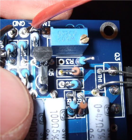
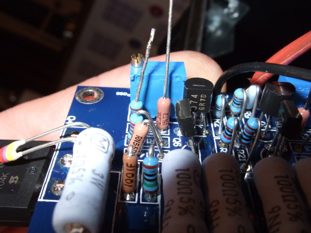
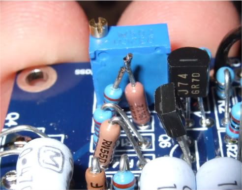
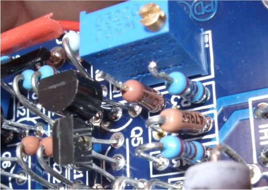
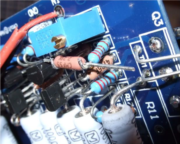
I had 2.2k resistors on hand, that's what I used. One channel has 4.4k total, one has 6.6k total.
I had 2.2k resistors on hand, that's what I used. One channel has 4.4k total, one has 6.6k total.
I have a desoldering gun thing so I can probably replace the resistor entirely without too much risk of lifting a pad. As pretty as your execution was. 🙂 I think I can find some resistors in the 6.6K range. I know I have some 10K. Is there a downside to going to high? Perhaps just less sensitivity from the pot, but that seems like not such a big deal.
Only add enough to get the Fets to bias properly. If you add too much you won't be able to turn it down enough...
Once it's working you could replace the resistor with a single one of the proper (whatever worked) value.
Once it's working you could replace the resistor with a single one of the proper (whatever worked) value.
Last edited:
Only add enough to get the Fets to bias properly. If you add too much you won't be able to turn it down enough...
.....
nope
pots are dominating in value , once you increase those resistors
Ok, my mistake. Then why not just begin with a much higher value resistor? It is to give the pot as much adjustment as possible, so the entire bias range isn't set within a single turn on a 10-turn pot?
well, trick is to leave as little you can to conduct through pot itself
not too much of importance in this case , but good engineering practice
not too much of importance in this case , but good engineering practice
Success! Went with 6.8k resistors and biased up beautifully with zero offset. Listened briefly with one channel and am already impressed! Will try to get the second channel done tonight.
- Status
- Not open for further replies.
- Home
- Amplifiers
- Pass Labs
- oneplustwo F5 build thread