Ok, here's a quick update...
SECOND CHANNEL:
I got the second channel put together but without the new rectifiers (haven't arrived yet.) However, I did add some heat transfer compound between the rectifiers and the sinks. That was... tricky since I didn't want to desolder and resolder the sinks and rectifiers. But I was able to access the trapped screws through the holes of the sinks in front of them. In any case I got it done, buttoned it back up, and voila! It works. They still get really hot AND they aren't smoking. Also, I measured ripple and it's a solid 17mV. No caps on the rectifiers. I figure they're rated for 15A so we'll use them unless I have good reason not to in the future.
We're still clearly in break in mode but it plays music quite nicely.
On DC offset, relative DC offset (+ to -) is still zero and absolute offset is about 7.7V. That's with the pot maxed out.
FIRST CHANNEL:
Speaking of absolute offset, for channel one, I adjusted VR2 to the max and get output to ground at 10V when warmed up. Can't get any lower than that. Relative DC offset from output + to - is essentially zero. Ripple is still solid at 18mV or less. Furthermore, I hear absolutely nothing from the speakers with no signal so I'm not worried about the ripple at all. The only sound I hear is a tiny bit of transformer hum.
Here's a pic of my temporary setup. Right now, path is macbook --> Emotiva XDA-1 --> hotrodded DCB1 --> Alephs.
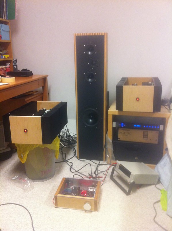
Sounds quite good actually already. Effortless is the best work I can think of at the moment. Lots of caveats of course... clearly biased, don't have golden ears, room setup is terrible, etc.
Thanks to everyone for their help. Special shout out to gl for the differential pairs!
Once I get my function generator, I'll play around with testing.
SECOND CHANNEL:
I got the second channel put together but without the new rectifiers (haven't arrived yet.) However, I did add some heat transfer compound between the rectifiers and the sinks. That was... tricky since I didn't want to desolder and resolder the sinks and rectifiers. But I was able to access the trapped screws through the holes of the sinks in front of them. In any case I got it done, buttoned it back up, and voila! It works. They still get really hot AND they aren't smoking. Also, I measured ripple and it's a solid 17mV. No caps on the rectifiers. I figure they're rated for 15A so we'll use them unless I have good reason not to in the future.
We're still clearly in break in mode but it plays music quite nicely.
On DC offset, relative DC offset (+ to -) is still zero and absolute offset is about 7.7V. That's with the pot maxed out.
FIRST CHANNEL:
Speaking of absolute offset, for channel one, I adjusted VR2 to the max and get output to ground at 10V when warmed up. Can't get any lower than that. Relative DC offset from output + to - is essentially zero. Ripple is still solid at 18mV or less. Furthermore, I hear absolutely nothing from the speakers with no signal so I'm not worried about the ripple at all. The only sound I hear is a tiny bit of transformer hum.
Here's a pic of my temporary setup. Right now, path is macbook --> Emotiva XDA-1 --> hotrodded DCB1 --> Alephs.
Sounds quite good actually already. Effortless is the best work I can think of at the moment. Lots of caveats of course... clearly biased, don't have golden ears, room setup is terrible, etc.
Thanks to everyone for their help. Special shout out to gl for the differential pairs!
Once I get my function generator, I'll play around with testing.
so one half will have 10V x Iq less dissipation , while other will have for same amount more dissipation
having both offsets zeroed ( after temp equilibrium) is a must
having both offsets zeroed ( after temp equilibrium) is a must
gimme exact schm you're using and I'll tell what to change
also put here exact value of offset between outputs and gnd , is it positive or negative
also put here exact value of offset between outputs and gnd , is it positive or negative
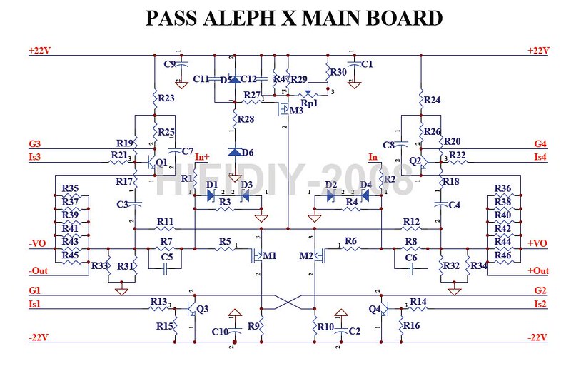
exact values for D5, R47,R29,Rp1 and R30
I presume that you set Rp to max (verify , please , with amp off) , and you can't out-gnd offset zero
how's that - you wrote somewhere in previous posts that both offsets are near zero , and now out-gnd offset is suddenly not ?
I presume that you set Rp to max (verify , please , with amp off) , and you can't out-gnd offset zero
how's that - you wrote somewhere in previous posts that both offsets are near zero , and now out-gnd offset is suddenly not ?
Sorry for not being clear. The dc offset from + to - was always zero. The dc to ground has always been near 10V.
I will confirm rp1 when I get home. But 99% sure it was fully counter clockwise.
I will confirm rp1 when I get home. But 99% sure it was fully counter clockwise.
Last edited:
....... The dc to ground has always been near 10V.
.......
that was exactly what I asked in first reply , after your post about dissipation difference
S......
I will confirm rp1 when I get home. But 99% sure it was fully counter clockwise.
that means nothing - it depends how you mount it - can be full value , or full zero ; that's why I asked for confirmation with ohm-meter
ZM - sorry, I should have made my post #120 more clear. In any case, at the risk of overstating... output to ground is -8 and -10 for each amp.
Also, I'm confirming the value of RP1 is at full value while counter-clockwise. I'm reading 150R while in place measuring at the points where R29 and R30 connect to it. When turned to full clockwise, it's zero.
The 150R reading confirms its roughly a 200R pot if I calculate the parallel resistances from R29, R30, and R47.
Are you also looking for the voltages across each of the items you mention above? Or just their part values?
If so... here they are:
D5: 8.92V
R47: 3.83V
R29: 4.84V
R30: 3.0V
Thanks in advance for your help!
desolder (pull out ) either R29 od R47 and then try entire procedure again
something is wrong with your measurement - voltage across R29 and R47 must be the same
something is wrong with your measurement - voltage across R29 and R47 must be the same
Slightly different numbers after an hour of warm up if it makes a difference:
D5: 8.99V
R47: 4.98V
R29: 4.99V
R30: 3.1V
During this commercial break... can I also confirm that it's important to turn on your source BEFORE turning on the amps? I noticed some pretty big turn on thump when I didn't initially have my source already one. Woofers extended outward pretty far... scared me a little bit but doesn't seem to have done any damage.
Last edited:
just do what I wrote in #131
regarding thump - that's normal , it doesn't have anything with your amp , but with common logic
regarding thump - that's normal , it doesn't have anything with your amp , but with common logic
Great, I'll give that a try tonight. Thanks for your help! I'm not really sure why both resistors are there in the first place... perhaps just power handling so as to not require higher wattage resistors? Or perhaps for people like me who just need an easy way to get to zero absolute DC offset? 🙂
dunno ;
someone was keen to put plenty of parts , probably to invoke better sound ?

properly sized R30 and Rp1 are all you need there , covering all possible variations
someone was keen to put plenty of parts , probably to invoke better sound ?
properly sized R30 and Rp1 are all you need there , covering all possible variations
Removed R47 and now when I turn the pots the OTHER direction fully, I can only get to +2.5 and +1.5 V. So it looks like I need to add another resistor back in. I should be able to find something in the ballpark. Any suggestions? Maybe something in the 100R range?
Also, I noticed the heat distribution is backwards now... although much more even now.
Also, I noticed the heat distribution is backwards now... although much more even now.
Last edited:
just thinking
if you now have out to gnd offset in positive (instead of previous negative ) , just put R47 back
but - this time not 475R ; put 1K for start then - if necessary - 910R or 820R
good night ..... 😉
if you now have out to gnd offset in positive (instead of previous negative ) , just put R47 back
but - this time not 475R ; put 1K for start then - if necessary - 910R or 820R
good night ..... 😉
Yes, that was what I was thinking. I'll try 1K first as you suggested. Thanks!
BTW, after fully warmed up, I have 1.6V and .3 V (positive on both) now. Seems to not be drifting anymore.
BTW, after fully warmed up, I have 1.6V and .3 V (positive on both) now. Seems to not be drifting anymore.
- Status
- Not open for further replies.
- Home
- Amplifiers
- Pass Labs
- oneplustwo Aleph X build thread