That is a nice build and it looks like you put the work into an original design. Kudos to you! I'd be too nervous to design my own fearing I might open up a blackhole or worse.
I am sure there are more than one way to skin a cat using a vacuum tube. I have see all kinds of iron being used from exotic NOS Tango/SANSUI to found in junk box iron to the Microwave Oven Transformers found on eBay. There exists an awesome pair of tube monoblocks that is closer to modern architecture than amp being built with 10 or 12 individual pieces of iron and it looks as good as it sounds and the comments were all over the map.
I have seen sand in the tube circuit being treated like sand in the vaseline and I don't get the reason why people act this way (I'd like to see if that argument works on Pete Millett's Engineer's Amp or not). DIY is personal preference, right?
I love seeing some outright jaw dropping builds and reading about the prototypes on boards with lifted traces from solder/desoldering with pics of the most confusing set up using the freakiest looking cracked glass red plating tubes with tops glowing white hot. I wonder if George ever gets thrown critical feedback versus the usual collaborative feedback? I bought from George the same pcb he was working on in those pictures because I wanted to give his design a try. George has pre-traced options for triode, UL, and pentode as well as tube or sand rectification.
End of the day, did your design work without burning down the house? Does it sound good to your ears? Yes?
Then, perfect. At times, you'd mistake this place for some where else.
Tjj226, thank you for the explanation. I made it clear at the outset that in this design I was following the lead of smarter people... like you.
Thank you for your kind words, but I can't take any credit. Just like you I stand on the shoulders of giants.
")
The #26 preamp thread has plenty of examples of people using these hammond chokes as plate loads if you wanna take a look.
156C: 150H, 3700 ohms, 8ma
This is the first I learned of this economical way to use cheap chokes. Would two 156C's come out to 300H total? In this circuit is 300H enough?
Depends on your definition of "enough".
The AC reactance of a choke is 2*pi*frequency*inductance in henries. Add the extra DCR of the winding to get the total impedance.
The plate resistance of the 1st half of a 13EM7 is about 40K. Lets say that we wanted a load with an impedance of 3X larger than the plate resistance. That means we are looking for an impedance of 120K or higher.
At 20hz, things aren't looking too good. If we plug 20hz into our formula we end up with 37,680 ohms. If we add on 6800 ohms of DCR, then our total load is 44,480 ohms.
Its about 80K at 40hz, and it gets to about 120K all the way at 60hz.
So yea, bass performance will suffer below lets say 60ish hz. This may or may not be a big deal depending on your speakers and your setup.
I personally prefer to use tubes with a plate resistance of 10K or below with the hammond tubes. I tried an O1A with the hammonds and it wasn't really spectacular.
Maybe the OP can add another two chokes in series for a total of 4? I haven't tested this myself to see if 4 chokes in series sounds ok or not, but I can't see why it would be too big of a problem. Hopefully one of the more knowledgeable members can share their opinions on whether or not this would be a good idea or not.
I would like to think adding more chokes would be a good idea because it would better isolate the preamp tube from the power supply. It would increase bass since there would be more inductance. And it would increase high frequency response since you are putting more winding capacitance in series. But im probably wrong in my thinking somewhere.
My comments:gem_piano:
1. I grew up in a house of musicians then married one.
2. Just because you ascribe to something a number does not mean you understand it in its entirety.
And no disrespect to all the engineers out there, I know I owe my very life to your calculations.
1. Good... we may presume that we both have educated ears!
2. True, but it's never just "a number". The "something" you allude to is invariably described by a vector, as in "X(vector) = x1+x2+x3+..." to as many dimensions (elements) as required, i.e. your "entirety". I agree, we may still not then fully understand the system.
But we are getting into the weeds...!
As you may have guessed, I am an engineer, also a musician (classical piano.) But we are off-topic from your triode amplifiers (for which I could argue several design issues)... so, just enjoy the music!
Cheers,
Roger
Tjj226, I think it was andyjevans in that 101 page thread from whom the notion came to me for the hum bucker use of the 156C and you are once again so correct that we all owe our greatest predecissors high honor for lifting us up to greater heights should we accept humbly the gift of their insight... and even thank those who tried and failed for those acts were needed too!
EDIT: Mea culpa! My nomenclature was wrong! You can't add "xi" of different dimensions, e.g. distortion in % and frequency in Hz, etc.... The "something" you allude to is invariably described by a vector, as in "X(vector) = x1+x2+x3+..." to as many dimensions (elements) as required...
By convention, a vector may be written: X = [x1, x2, x3, ...], or they can be in a column (depends on the mathematical application.)
Cheers,
Roger
The build is very nice & would not result in ones other half throwing it out.
OTOH, the electrical design looks like the result of a serious dumpster dive.
Choke & transformer loading of triodes was common in the 20s & 30s but not on high mu triodes. Was always on triodes of mu of 20 or less. High mu triodes have too high plate resistance to drive properly into a choke.
The Hammond 157C has lots of inductance to work with but will have some parallel winding capacitance included. That usually results in a resonant peak somewhere in the audio frequency results. High mu triodes were developed to eliminate the chokes & transformers from the low level parts of the audio path.
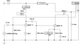
I would be suspicious of your 'hum bucking' connexion of the two Hammond 157Cs. I've used a 157C as a hum field detector. Not as good as the real thing, but they respond to AC magnetic fields very well. Are you sure the chokes a not simply detecting the field radiated by the power transformer?
Is the PT simply a 120V/120V isolation transformer? I suspect it is.
The specs of the output transformer will be the limit of the lower & upper frequency response. Is there a spec for the primary & leakage inductances?
Using fixed bias on a low level voltage amplifier is not a good solution. As the tube ages the bias will no longer be ideal. Cathode bias fixes that problem & avoids an aging battery problem as well. There is plenty of gain in this cct, an unbypassed cathode resister would work well. Looks like your amp would deliver a little more than one watt.
Your power supply has 'brute force' smoothing. The H157ZA does not make much sense at the current level in this design. But if they were got for free, why not? But then requires a horrendous cap bank to make up for the inductance shortage.
But all looks nice anyway.
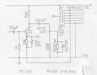
I built two versions of this kind of amp 20 yrs ago. From memory the 6EM7 vers made 3W on a 250V supply. There was a following amp using a 6LU8, so could run triode or UL. It managed 5W in UL mode.
Both were published in Glass Audio Magazine.
OTOH, the electrical design looks like the result of a serious dumpster dive.
Choke & transformer loading of triodes was common in the 20s & 30s but not on high mu triodes. Was always on triodes of mu of 20 or less. High mu triodes have too high plate resistance to drive properly into a choke.
The Hammond 157C has lots of inductance to work with but will have some parallel winding capacitance included. That usually results in a resonant peak somewhere in the audio frequency results. High mu triodes were developed to eliminate the chokes & transformers from the low level parts of the audio path.
I would be suspicious of your 'hum bucking' connexion of the two Hammond 157Cs. I've used a 157C as a hum field detector. Not as good as the real thing, but they respond to AC magnetic fields very well. Are you sure the chokes a not simply detecting the field radiated by the power transformer?
Is the PT simply a 120V/120V isolation transformer? I suspect it is.
The specs of the output transformer will be the limit of the lower & upper frequency response. Is there a spec for the primary & leakage inductances?
Using fixed bias on a low level voltage amplifier is not a good solution. As the tube ages the bias will no longer be ideal. Cathode bias fixes that problem & avoids an aging battery problem as well. There is plenty of gain in this cct, an unbypassed cathode resister would work well. Looks like your amp would deliver a little more than one watt.
Your power supply has 'brute force' smoothing. The H157ZA does not make much sense at the current level in this design. But if they were got for free, why not? But then requires a horrendous cap bank to make up for the inductance shortage.
But all looks nice anyway.
I built two versions of this kind of amp 20 yrs ago. From memory the 6EM7 vers made 3W on a 250V supply. There was a following amp using a 6LU8, so could run triode or UL. It managed 5W in UL mode.
Both were published in Glass Audio Magazine.
Attachments
.....results in a resonant peak somewhere in the audio frequency.....
Yes, but damped by tube plate resistance. So it is essentially flat from below 80Hz to somewhere above 8kHz depending on actual C value. For the technology, that's not so bad.
(This is probably more limiting than the OT.)
Fix-bias on the voltage amp makes current an easy function of B+ and rp. At a higher supply, burn-up can happen. Probably not with this wee 160V.
To my taste, this ticks all the "wrong" buttons. (I did a 13EM7 design long ago but can't find it.) But in DIY context I don't see any reason it won't work, and maybe happy. If 80Hz-8kHz is not enuff it is easy to put a resistor in place of the chokes.
- Status
- This old topic is closed. If you want to reopen this topic, contact a moderator using the "Report Post" button.
- Home
- Amplifiers
- Tubes / Valves
- One Tube Mono Blocks