Zebra100, thanks for your comments. I was under the impression that star grounding is necessary when one is using one transformer and one rectifier board for a stereo configuration but not if you are using two transformers and two rectifier boards. You seem to imply otherwise. Did I misunderstand you?
I have my amp boards mounted side by side in the chassis. I have connected both channel ground points (CHG) together using some 2.5mm silver plated solid copper wire, which I fashioned into bar across both PCB's (I did have to file the ends a little to get it to fit into the holes on the PCB). I then used the bar as my star earth point; soldering the wires from PG+ and PG- on rectifier boards (using standard equipment wire), and a wire to the chassis earth point; 5 wires in total. V+ and V- are connected to the amp as normal.
I have a picture somewhere. When I find it, I will post it here.
The amp is absolutely silent with no input signal.
I have a picture somewhere. When I find it, I will post it here.
The amp is absolutely silent with no input signal.
Thank you, Zebra100. This is a very helpful and very kind of you to take the trouble of opening up your amp.
Hi,
Thank's Zebra100, very interesting..
Actually I build a dual mono amp, LM3886 from Chipamp.
I add a safety loop breaker, schematic of Rod Elliot :
http://sound.westhost.com/earth-f4.gif
Do you think my setup is correct ?
Thank's in advance.
Phil.
Thank's Zebra100, very interesting..
Actually I build a dual mono amp, LM3886 from Chipamp.
I add a safety loop breaker, schematic of Rod Elliot :
http://sound.westhost.com/earth-f4.gif
Do you think my setup is correct ?
An externally hosted image should be here but it was not working when we last tested it.
Thank's in advance.
Phil.
Do you think my setup is correct ?
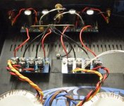
Does the transformer mounting create a shorted turn in them?
Not just between the two transformers, but also to the chassis.
Your earthing is also wrong and dangerous. The inlet earth tag must connect directly to chassis. The loop breaker then goes between signal grounds and your earth point.
Your earthing is also wrong and dangerous. The inlet earth tag must connect directly to chassis. The loop breaker then goes between signal grounds and your earth point.
Last edited:
Thank's..
>> The inlet earth tag must connect directly to chassis.
Yes it is, but not visible on picture..
But you are right, bar between the two transformers seems not good.. I had a doubt about that.
How could I proceed ?
Remove earth cable (yellow/green) of the bar and connect earth directly to the chassis ?
Or remove the bar ?
Phil.
bar between the two transformers seems not good..
As was mentioned before, not only between the 2 transformers, but you also should not create a metallic loop around the transformer as voltage is inducted in it. It acts as a secondary winding.
Just throw all the bars in the bin.
If the transformers have electrostatic screen (they do not appear to have) then connect that to your IEC inlet earth tag.
Using chassis as a ground connection scheme in audio is never a great idea. It's not that great in cars either...
If the transformers have electrostatic screen (they do not appear to have) then connect that to your IEC inlet earth tag.
Using chassis as a ground connection scheme in audio is never a great idea. It's not that great in cars either...
Phil,
Having a safety earth isn't a bad thing; just make sure your inlet earth goes directly to the chassis. As others have said, your transformer mounting setup is a big problem. There will be all sorts of issues with induced currents between the chassis and transformers; especially at switch on with the large amount of inrush current. I'd be very surprised if you don't blow primary fuses at switch on.
The bolt and washer arrangement is more than sufficient to hold the transformers in place. Get rid of the bars completely.
As for the star earth, all the ground connections from the PSU boards (PG+/PG-) and CHG from both amp boards should all be connected together a some point close to the amp boards, with a separate connection from that point to a chassis earth point; in your case the safety earth.
(Edit) Just another quick point about chassis earth points and mains power connectors; All connections should be mechanical i.e crimped, to avoid potential problems caused by overheating connections. You wouldn't want a wire to fall off due to the solder melting.
Last edited:
Thank's all !!
New mounting with a piece of plywood :
Then using nylon screws for transfos was a little better..
I note about soldering and connections.
Transformers have not electrostatic screen, it's isolated "class 2", and normally they do not require earth grounding, but by security, I prefer have.
Phil.
New mounting with a piece of plywood :
An externally hosted image should be here but it was not working when we last tested it.
Then using nylon screws for transfos was a little better..
I note about soldering and connections.
Transformers have not electrostatic screen, it's isolated "class 2", and normally they do not require earth grounding, but by security, I prefer have.
Phil.
The Chassis whether of steel, or aluminium, or copper makes an excellent screen.Just throw all the bars in the bin.
If the transformers have electrostatic screen (they do not appear to have) then connect that to your IEC inlet earth tag.
Using chassis as a ground connection scheme in audio is never a great idea. It's not that great in cars either...
You can connect the various compulsory connections to different locations on the screen.
The screen connects to Earth by capacitance, not by cable.
The screen PE connects to Neutral via the PE wire in the cable.
Toroids without an electrostatic screen have NO provision for earth grounding......Transformers have not electrostatic screen, it's isolated "class 2", and normally they do not require earth grounding, but by security, I prefer have........
No part of the primary, nor the core, is available/exposed to make a grounding connection.
The power supply and signal earth of each channel will still be linked; either at the chassis or the mains earth in your building power supply. Even if you build true monoblock amplifiers, the transformer primary coils will still be effectively connected in parallel at your mains fuse board (or ring main/spur).
The only way to truly isolate the power supplies is to have each channel on a separate phase, but then there may be slight differences in phase voltages unless you are using a regulated power supply regenerator, which is overkill for any Hifi amp.
The only way to truly isolate the power supplies is to have each channel on a separate phase, but then there may be slight differences in phase voltages unless you are using a regulated power supply regenerator, which is overkill for any Hifi amp.
What if you used two safety loop breakers? One per transformer/channel.
A pair of monoblocks do not have a commoned signal ground forming a loop.Even if you build true monoblock amplifiers, the transformer primary coils will still be effectively connected in parallel at your mains fuse board (or ring main/spur).
The two amplifiers with their inputs and outputs are completely independant.
A dual mono amplifier does have a commoned signal ground that does form a loop
Two Disconnecting Networks insert a current reducing device into each of the two loop halves.
It's this current reducing that attenuates the interference in the signal cabling.

- Status
- Not open for further replies.
- Home
- Amplifiers
- Chip Amps
- one or two transformers