Or place the middle of 3 flat on the bottom of the PCB, i was under the assumption that the boards are plated through.
The additional 10 mm length doesn't look like a problem.
I've tried both MKC1813, MKC1860 and MKC1862, even bought a large batch of 10uF/63V MKCs Roedersteins for nickels and cents last year. As a coupling cap i'm not impressed by MKC.
The additional 10 mm length doesn't look like a problem.
I've tried both MKC1813, MKC1860 and MKC1862, even bought a large batch of 10uF/63V MKCs Roedersteins for nickels and cents last year. As a coupling cap i'm not impressed by MKC.
Jacco,
I may have to try different options for implementing larger sized caps...
You are absolutely right with MKC! Not my first choice either...KP-type capacitors at 10uF are too big and way too expensive.
Just as a question... does anyone know what Nelson used in his original P?
It has been so long since I got my hands on one (and at the time I was not even thinking about building one...)
From pictures, they look very much like Panasonic ECQ-P-type but as it seems, they don´t do 10uF...?
Sorry guys,
either I am too clumsy or else...
No can do. No way I can fit WIMA MKP4s on the board.
I think I still have some EPCOS MKP 10uF someeeewhhhhheeeeeere......iinnnnn.... a.........drawaer.
Hang on! I am looking for them...
either I am too clumsy or else...
No can do. No way I can fit WIMA MKP4s on the board.
I think I still have some EPCOS MKP 10uF someeeewhhhhheeeeeere......iinnnnn.... a.........drawaer.
Hang on! I am looking for them...
My question was because I know I can fit 3.3uF and maybe even 4.7uF Rifa PHE426s on the boards, but I am not sure if it is enough (total input/output capacitance would then be 3.3/9.9 uF or 4.7/14.1 uF) The backup plan is to bypass the MKPs with 4.7uF BG N-caps, but I'm not really sure it's necessary.
/U.
/U.
Designing this board I was thinking more about Black Gate N at input and output than any other capacitors so there is not much space (this keeps board quite small). If You wont to invest good - go for BGN. Relation between space / cost / quality is great.
Original AP1.7 works with relay volume control - impedance on output is changing from ohms to kohms. This means that capacitors must have considerable values.
For example if You use normal 10k pot at the output You can safely lower capacitor values.
All of resistors in my amplifier are ELPOD 0.5%/50ppm 0.25W or 0.5W. They are only available in Poland for special order 😉
Allright, that explains it. Thanks Damian 🙂veteran said:Original AP1.7 works with relay volume control - impedance on output is changing from ohms to kohms. This means that capacitors must have considerable values.
For example if You use normal 10k pot at the output You can safely lower capacitor values.
/U.
PS filtering and C6/C5 are basing on PANASONIC TSHA 1000uF/100V caps. They are available in DigiKey.
One more thing about finding good signal caps and values - EXPERIMENTS 😉
One more thing about finding good signal caps and values - EXPERIMENTS 😉
Mach.88:
I'd be very interested in knowing the results of your experiments using "standard" and "exotic" parts in your two Aleph P 1.7 preamps. When do you anticipate finishing the projects?
Regards,
Scott
I'd be very interested in knowing the results of your experiments using "standard" and "exotic" parts in your two Aleph P 1.7 preamps. When do you anticipate finishing the projects?
Regards,
Scott
Hey Scott (still seeking for Eton 12" drivers 😉 ),
I may be done in 3 weeks from now. One set of boards is finished but I still have to go through the matching process and as I also do a couple of Onos (same type of experiment, standard and exotic components), I am looking at many IRF 9610 and IRF 610 to be matched.
Also I have not made up my mind yet whether to use a relais-volumecontrol or a ELMA based switch...
I will keep you all posted
Transistor matching
Maybe you guys can help me out here....
Out of all the transistors (ztx450/ztx550//IRF610/IRF9610) and possibly even resistors, what items should be matched... and to what tolerances.
Cheers
Maybe you guys can help me out here....
Out of all the transistors (ztx450/ztx550//IRF610/IRF9610) and possibly even resistors, what items should be matched... and to what tolerances.
Cheers
Re: Transistor matching
Thanks for pointing out the link to a Passdiy article. But the question is WHAT to match not how.
I have it on good authority, all transistors are to be matched to within 0.1V or if you have a large population to work with 0.01V. To those that have built the amp please give us your comments.
Wasineveritis said:
Thanks for pointing out the link to a Passdiy article. But the question is WHAT to match not how.
I have it on good authority, all transistors are to be matched to within 0.1V or if you have a large population to work with 0.01V. To those that have built the amp please give us your comments.
T4 = T6 and T5 = T7
How about transistors T4 = T6 and T5 = T7? Do we match transistors?
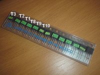
veteran said:You have to match all MOSFETs in this design into a couples: (one channel) T1 = T8, T2 = T9, T3 = T10. For example:
How about transistors T4 = T6 and T5 = T7? Do we match transistors?
kmj said:Just transfered money to Veteran 😀
Ken, Veteran
I received my boards today. Many thanks,
Steve
veteran said:there is not much space
I see what you mean, just received my set of boards.
I managed to squeeze in one 10uF MKC and two 4.7uF Wima MKP4 with 27.5 mm leads spacing.
Doing the same on the bottom of the pcb should give ~19 uF in MKP and 20uF in MKC, or a total of close to 30uF with MKP on the bottom only. (does mean i am 10 of those MKP4s short right now)
Veteran, thank you for the design and the boards.
- Status
- Not open for further replies.
- Home
- Group Buys
- (one more) ALEPH P 1.7 clone