I need your kind help with one challenge I have. I call it a challenge as I am in disdain and not experienced with BJT-circuits design.
Topic: I would like to use one-BJT (not two or more) for providing a single audio Line Out from many sources Inputs of various output impedance (some are low, some are high) via a switch. Practically it should be a buffer with much larger input impedance than any of the inputs, I softly guess.
Now, comes the hard part of the request:
Of course, I could use the switch alone, but the sources are not properly buffered and I am afraid not to mess them up.
The input signal amplitudes are scaled to 1.0V (0dBuRMS)
I have a +18V PS, regulated.
The one-BJT can be NPN or PNP, whichever. I can care less about this.
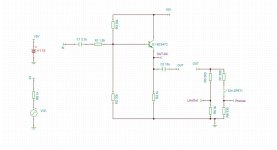
The first attempt I made it ended lousy: I used a BC547 with CC topology. The output signal has 2-nd harmonic (-40dB) already present even at low amplitudes. At around 0.5V amplitude it started to show huge distortions, both even and odd. Examination show that the positive side are softly compressed, enough to get now ALL harmonics at around -40dB.
Attached the CC-topology I used. The simulations did not show these distortions.
The measured DC voltage on emitter is indeed 8.5V as simulated.
Any hints? What I did wrong?
Is it at all possible to fulfill the above requirements with only one BJT?
Which topology and schematic/components would be better (still one-BJT topic frame)?
P.S. I saw too late that my title is a bit off. This is not a mixer, rather a line buffer. Sorry.
Topic: I would like to use one-BJT (not two or more) for providing a single audio Line Out from many sources Inputs of various output impedance (some are low, some are high) via a switch. Practically it should be a buffer with much larger input impedance than any of the inputs, I softly guess.
Now, comes the hard part of the request:
- SNR: > 100dB
- THD @ 0dB: < 80dB for even, and <90dB for odd ones
- headroom: 14dB (amplitude 5V)
Of course, I could use the switch alone, but the sources are not properly buffered and I am afraid not to mess them up.
The input signal amplitudes are scaled to 1.0V (0dBuRMS)
I have a +18V PS, regulated.
The one-BJT can be NPN or PNP, whichever. I can care less about this.
The first attempt I made it ended lousy: I used a BC547 with CC topology. The output signal has 2-nd harmonic (-40dB) already present even at low amplitudes. At around 0.5V amplitude it started to show huge distortions, both even and odd. Examination show that the positive side are softly compressed, enough to get now ALL harmonics at around -40dB.
Attached the CC-topology I used. The simulations did not show these distortions.
The measured DC voltage on emitter is indeed 8.5V as simulated.
Any hints? What I did wrong?
Is it at all possible to fulfill the above requirements with only one BJT?
Which topology and schematic/components would be better (still one-BJT topic frame)?
P.S. I saw too late that my title is a bit off. This is not a mixer, rather a line buffer. Sorry.
Attachments
Last edited:

Please also see https://www.diyaudio.com/community/...transistor-power-amplifier-with-thd-1.406538/
Probably the best possible, imo.
Probably the best possible, imo.
Thinking about your question, not sure I have a good answer to your goals, but I can fix the title of the thread. 😀
Attached the CC-topology I used. The simulations did not show these distortions.
The measured DC voltage on emitter is indeed 8.5V as simulated.
Any hints? What I did wrong?
Depending on the layout and the power supply decoupling, it might be oscillating, usually at 200 MHz...300 MHz. If it oscillates, the oscillation builds up until something starts to clip, and when that happens, it will typically distort like crazy.
Is it also supposed to be a headphone amplifier?
yesIs it also supposed to be a headphone amplifier?
I will check oscillations and be back with info this evening.
Thanks everyone! Also for the hint on other previous work here.
It takes a lot of bias current and dissipation to meet the requirements. Perhaps you would need MOSFET to ensure high enough input impedance.
Why insist on a single transistor? With few plus transistors you can solve many issues.
Why insist on a single transistor? With few plus transistors you can solve many issues.
My bet for schematic in OP:
R1 = 0
R3 = 4k7
R2 = 10k
R4 = 330R 5W
Q1 = BD139 or similar, heatsink recommended
perhaps a base resistor of 56-100R
R1 = 0
R3 = 4k7
R2 = 10k
R4 = 330R 5W
Q1 = BD139 or similar, heatsink recommended
perhaps a base resistor of 56-100R
If you should use it for headphone.
What headphone impedance do you have?
Different headphones have different needs.
So, to build the amplifier we need to know more about headphones.
I see you use 18V supply. That is good.
BD139 is abetter choice. This allows more current into Phones.
What headphone impedance do you have?
Different headphones have different needs.
So, to build the amplifier we need to know more about headphones.
I see you use 18V supply. That is good.
BD139 is abetter choice. This allows more current into Phones.
Last edited:
I am repurposing an old board and this is what I got left for Line out (and eventually Phones).Why insist on a single transistor? With few plus transistors you can solve many issues.
The Line Out has priority. With Phones disconnected the Line Out is wished to give a THD<80, sufficient linearity for 5V overhead and a SNR>100dB.
@lineup
If Phones are shortly connected (300-600Ohm types), a trade-off for Line Out performance is expected. This mode is not supposed to be used usually or at all. Better/dedicated headphones amp is available. This "phone output" is only for service. Prio 1 is the Line Out function.
now:
- I was thinking to BD139 as well, but noise below 1KHz is of concern.
- MOSFET: LF noise issues?
- more than 18V: only up to 24V is possible without big changes.
@Elvee
What is your THD expectation for PS18V, IN1V and BC547? BC337? BD139?
Will go now to look into oscillations. Problem is, I have only a 40MHz oscilloscope (the one with 400MHz I can borrow later).
How to kill them? 100pF on Base-Colector pins would do? Less? More?
If not possible to tam the oscillations, then I will check Chip_mk's bet and the Lineup's BD139 idea.
An emitter follower with constant current load could work - use constant-current diode (or diodes) to set the quiescent current to the level you want.
That's a very limiting constraint of course. Presumably this rules out using Darlingtons?I would like to use one-BJT (not two or more)
Actually I am limited by the footprint (3 through holes) and topology already on PCB (the one shown here). The Darlington is a good idea if the other requirements (THD and SNR) will be fulfilled. Again, I do not know ho to properly compute such thing.That's a very limiting constraint of course. Presumably this rules out using Darlingtons?
Again, I do not know ho to properly compute such thing. Can you please exemplify/hint me the schematic?
I can theoretically cut the collector trace, to insert a resistor there and go into other topologies. But, this is invasive (still not off of the table).
One can also think of Voltage regulators, as I remember on this thread reading a few years ago how the best chip-amp is a 3-pin voltage regulator 🙂
Opinions?
In principle, anything that has 3 pins and can use the existing holes from BJT bias resistors and decoupling caps , is accepted.
With 2 BJT: BC547 + BD140 it is possible to get low THD.
I am afraid this is not possible with only one BJT.
I am afraid this is not possible with only one BJT.
Sounds quite reasonable if I understand your idea correctly. But sorry, not a BJT expert here. I do not know how to design this with BJT.An emitter follower with constant current load could work - use constant-current diode (or diodes) to set the quiescent current to the level you want.
Can you please send me link or exemplify with a photo? Or even a text walk through would work, I guess.
It will mostly depend on the load(s) compared to the emitter sink resistance.What is your THD expectation for PS18V, IN1V and BC547? BC337? BD139?
It should be around 0.1%, provided the circuit is dimensioned properly, and it will depend very little on the transistor type, due to fundamental physics.
The Early voltage will have a small effect, but that's about it.
To gain more linearity, you need to maximise the quiescent current compared to the load current (and you might need a beefier transistor than a BC547 to do that).
Increasing the supply voltage will also gain you more linearity (but it will also increase the dissipation).
A LM317 could operate as an almost perfect follower if you use the adjust pin as input (if you search, you will find many amplifier projects of mine based on voltage regulators).
Their main weakness is their slowness, but for the audio band they are just sufficient
A current source will normally add at least one transistor.
That's easily solved when that transistor is a junction field effect transistor that the manufacturer calls a constant-current diode 😉
Guys, as much as I love your ideas and expert ping-pong, I really wish to ask you to focus on Prio-1: l Line Out function.
@Elvee : The Headphones is really a secondary thing, I can drop it in a heart beat, to preserve THD and SNR.
@Elvee : I will look into LM317. Do you have a particular topology/link in mind?
@MarcelvdG : will look for using FET with 2 terminals connected (Const Current Source). Do you have a particular topology/link in mind?
@Mark Tillotson : yes to Darlingtons (Sziklay too?) Do you have a particular topology in mind?
@lineup : 'With 2 BJT: BC547 + BD140 it is possible to get low THD.' Does this sounds like Darlington solution?
@gannaji : I started to look into the link you gave. Nice!
@chip_mk : will test the values tomorrow. Today was not possible.
Thanks to all for help so far, and for very fun and educational reading!
Limiting your circuit to one transistor is no different from limiting it to one resistor or one capacitor. Signal transistors cost pennies and take no more space than resistors or caps.
If you want something very simple, a dual op-amp (~TL072) will do a better job than your single EF circuit in less space. A high current op-amp will drive 30 or even 8 Ohms. TI sells a long list of "headphone amp" chips, but I am not a fan of proprietary chips.
Audiophiles at DIYA post elaborate "headphone amps" for PPM distortion but your EF circuit is nowhere close to that. I am happy with 0.01%THD but your EF will not do that either, at ~2VRMS.
I recommend playing with LT spice (for free) and you will find that multiple device circuits are not rocket science, and you can try several ideas before you spend any money on parts.
@steveu
Sure, true. That I know very well myself. I can design many ways an OpAMp for doing this task in a heart beat. Actually it would only take as far as to look into my drive.
I have LTSpice and recommended it to my HW colleagues 20 years ago. Somehow they got stuck with it. I switched to TinaTi. Question of taste... and also I work more with TI than with Analog. One important criteria was that Tina is more calibrated (simulations match reality). I did not 'calibrated' LTSpice, as lack of time. So the choice.
Now I have a one-off hobby-task in decades to stick to BJT design, which I am in disdain for its math 🙂 More, to one-BJT footprint + bias (which is quite a challenge for these requirements). I appreciate your help to get me through it and get good or decent performance with this choice 🙂
Actually I like it in particular that it gets me to know all of you here better. You are fun and pleasure to work with, to learn.
Last edited:
- Home
- Source & Line
- Analog Line Level
- One BJT line amp/buffer