Post19 pic2 (the lower one).
Note the VERY IMPORTANT gap or link between the Zero Volts on the PSU and the Star Ground. This link must never be omitted.
Never put the Star Ground (I call it Audio Ground) on the PSU.
BTW,
the 2k resistors increase the ripple on the supply lines.
Some of that added ripple can get through a Power Amplifier and come out as hum on very low level signals.
Last edited:
there is the 4 coil, 4 rectifiers option if you are so inclined....
and in addition you can use separate transformers for each channel in a stereo setup, unless what you are building is a mono amp....😀
he is building UcD2K. so i guess 1 ch🙂
and as Andrew said. starground it on the amp board.
and as Andrew said. starground it on the amp board.
Last edited:
I did not say
I said
starground it on the amp board
I said
Never put the Star Ground ............... on the PSU
well. the amp board have a star ground point. so making one between the amp board and PSU is pointless🙂
Which post says, or shows that?.............the amp board have a star ground point. .....................
andrew. no post in this thread that says it or shows it. i just know it🙂
all hypex amp boards have a star ground point🙂
all hypex amp boards have a star ground point🙂
Plans are using Hypex UcD2k driving a couple of sealed subwoofers based on CSS Trio12
andrew. i think i am in the correct tread🙂
Hello,
Can the Plus and Minus of two bridge rectifiers be placed in series with the AC connections tied to two different transformers? Basically, I'm try to gain more current. One transformer is a Single Pri and Single Sec. The other transformer is Single Pri and double secondary. I want to get current from the single Sec and also from one of the dual secondary windings and tie together for my load? The other dual secondary winding will be used for something else with one of the windings tied to AC Neutral.

Can the Plus and Minus of two bridge rectifiers be placed in series with the AC connections tied to two different transformers? Basically, I'm try to gain more current. One transformer is a Single Pri and Single Sec. The other transformer is Single Pri and double secondary. I want to get current from the single Sec and also from one of the dual secondary windings and tie together for my load? The other dual secondary winding will be used for something else with one of the windings tied to AC Neutral.
Not use it.... since you could effectively configure each traffo for 1/2 side of the dual rail voltages? Yes?and how can you paralell the sec on a center tap transformer?
Last edited:
Charlie,I suggest that you don't connect the two banks of caps together until the end farthest from the transformer, and then connect them together at one point, where you will also connect the earth ground. This will reduce hum and provide a star ground point.
Instead, do it like this (the part of the circuit to the right of the two diode bridges):
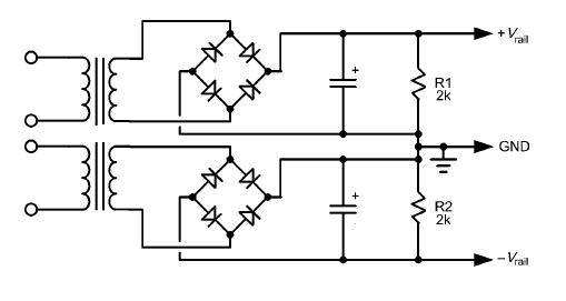
The rest of your sketch looks fine... you might want to include some snubbers on primaries and/or secondaries...
-Charlie
I want to do the same thing so that I can double up on my current. Except my traffos will have a CT. Your drawing did not take into account a CT secondary. I have a single rectifier and filter PSU I want to use so neither drawing applies to my scenario too. Can I simply parallel the secondary windings (including the CT) without any ill-effect? My traffos will be identical so there should be no fighting for current, or need for ballast resistors.

P.s. Since I need dual rail voltages, I guess I could dispense with the CT (tie them off and not use them), and feed my single bridge rectifier from both traffos. Would that work?
From experience the two transformer approach is not as good as a single transformer. If both transformers are identical, and mine were, then the maths would suggest that you can use them in series as you are proposing. But for some reason I ended up with a very poor response from my amplifier with a two transformer set-up.
I've never done this before, hence my question. I just want to be sure before I hook something up wrong and blow a circuit! 🙂 BTW, I wasn't going to use them in series, but rather in parallel, where the voltages would be the same, but double the current potential. I'm just not sure of the electrical interactions (if any) of the 2 traffos in that kind of situation. It's been decades since I had transformer theory, so as I'm rusty I don't want to second guess myself. 😀 My other option is to abandon the single rectifier and filter circuit altogether and go with two instead - in a pure dual mono PSU mode. Then there would be no issue.From experience the two transformer approach is not as good as a single transformer. If both transformers are identical, and mine were, then the maths would suggest that you can use them in series as you are proposing. But for some reason I ended up with a very poor response from my amplifier with a two transformer set-up.
Last edited:
What is the optimal config...
With a pair of dual secondary 500va transformers in a 2 channel amp, what is the recommended configuration?
= mono block with one transformer per channel, its secondaries in series, or
= single power supply with one transformer per rail, its secondaries paralleled
I am building Jen's 10 output Leach clone but with thermal traks. With rails of 75V and a 6 to 12 ohm speaker load the amp will clip before I use all of that 500VA so there seems little point to use option 2 with its higher current capability.
The only advantage of dual mono construction is the separated secondary windings.
If you parallel the windings in the two transformers you instantly lose that only advantage and you already have the inherited consequences of going dual mono instead of mono block.
If you parallel the windings in the two transformers you instantly lose that only advantage and you already have the inherited consequences of going dual mono instead of mono block.
Could you elaborate on the 'inherited consequences' of dual mono?The only advantage of dual mono construction is the separated secondary windings.
If you parallel the windings in the two transformers you instantly lose that only advantage and you already have the inherited consequences of going dual mono instead of mono block.
- Status
- Not open for further replies.
- Home
- Amplifiers
- Power Supplies
- One amplifier, two transformers