Hi,
I have two big toroid trafos (1000VA 2x65V). I would like to use both of them to power one amplifier, but I want them to share the same capacitor bank.
There's different ways doing this. What's the pros and cons of each?
What I had in mind:
1, Connect all four secondary windings to their own bridge rectifier and parallel it afterwards. A total of four rectifier bridges.
2, Connect the secondary windings of each trafo in parallel and use one rectifier bridge for each trafo. A total of two rectifier bridges.
To clarify, two transformers, each with double secondary windings. One shared capacitor bank. One amplifier. Dual power supply.
Maxhax
If you are certain that the two transformers are completely identical then you might get away with paralleling their secondaries. If not, you will have to use ballast resistors to encourage current sharing. Using separate bridges means you will need to ensure identical bridges and maintain identical temperatures (not easy) as the hotter bridge will take more current and heat up even more, or use even bigger ballast resistors.
If the transformers are not identical then ever bigger still resistors are needed.
If the transformers are not identical then ever bigger still resistors are needed.
If you are certain that the two transformers are completely identical then you might get away with paralleling their secondaries. If not, you will have to use ballast resistors to encourage current sharing. Using separate bridges means you will need to ensure identical bridges and maintain identical temperatures (not easy) as the hotter bridge will take more current and heat up even more, or use even bigger ballast resistors.
If the transformers are not identical then ever bigger still resistors are needed.
He is right- the two transformers will end up fighting over current!
hmm, fighting over the current...
Is that the case even if its the same transformer, only paralleling the windings. Each side of the amplifier driven by one transformer each?
The trafos are exacly the same, custom hand made transformers.
Plans are using Hypex UcD2k driving a couple of sealed subwoofers based on CSS Trio12
Is that the case even if its the same transformer, only paralleling the windings. Each side of the amplifier driven by one transformer each?
The trafos are exacly the same, custom hand made transformers.
Plans are using Hypex UcD2k driving a couple of sealed subwoofers based on CSS Trio12
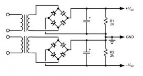
I think your #2 is fine. I sketched this out in the attached schematic. It's two separate power supplies, one for the + rail and one for the - rail, that are connected together at the caps with the earth ground to set potential.
-Charlie
-Charlie
Attachments
Exacly, a normal dual rail power supply.
It should be possible to just parallel the secondary windings as long as I make sure that the phase is proper aligned, right?
It should be possible to just parallel the secondary windings as long as I make sure that the phase is proper aligned, right?
Are the transformers center tapped? If so use one for the + rail and one for the negative rail. you will only need 4 diodes total
Exacly, a normal dual rail power supply.
It should be possible to just parallel the secondary windings as long as I make sure that the phase is proper aligned, right?
Right. It's not "phase" per se, it's the connection as parallel or anti-parallel.
Are the transformers center tapped? If so use one for the + rail and one for the negative rail. you will only need 4 diodes total
and how can you paralell the sec on a center tap transformer?
and how can you paralell the sec on a center tap transformer?
and how can there be FOUR secondary windings (on two transformers) if they are center tapped?
Read post #1 again. I believe that the transformers each have two separate secondaries.
and how can there be FOUR secondary windings (on two transformers) if they are center tapped?
Read post #1 again. I believe that the transformers each have two separate secondaries.
i know that. but i wanted to hear how he ment to get a single 65V 1000VA
from those transformer if they was 65-0-65V type🙂
Indeed, two trafos, each trafo have two secondary windings 65-0, 65-0
As long as I keep the two windings "in phase" I shouldnt have any problem connecting it to a normal diode bridge right? Will there be currents flowing and trafos buzzing?
As long as I keep the two windings "in phase" I shouldnt have any problem connecting it to a normal diode bridge right? Will there be currents flowing and trafos buzzing?
Indeed, two trafos, each trafo have two secondary windings 65-0, 65-0
As long as I keep the two windings "in phase" I shouldnt have any problem connecting it to a normal diode bridge right? Will there be currents flowing and trafos buzzing?
Once you connect the secondaries in parallel, they act like a single secondary. My diagram shows how to connect these to a diode bridge, caps, and the earth ground.
Charlie
Yes, the best way to do it is to parallel the secondaries on one transformer for the + rail, and the other one for the - rail. I should have thought of that. Like most bright ideas it seems obvious once someone has suggested it.
If they are really 'hand-made' then check the secondary voltages before you parallel them, just in case one accidentally got an extra turn round the core.
If they are really 'hand-made' then check the secondary voltages before you parallel them, just in case one accidentally got an extra turn round the core.
That is sub-optimal where there are two secondaries, although necessary if there is only CT winding. It is suboptimal because it avoids the opportunity to halve secondary resistance which paralleling provides.
Looks okey?

I suggest that you don't connect the two banks of caps together until the end farthest from the transformer, and then connect them together at one point, where you will also connect the earth ground. This will reduce hum and provide a star ground point.
Instead, do it like this (the part of the circuit to the right of the two diode bridges):
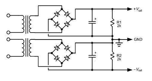
The rest of your sketch looks fine... you might want to include some snubbers on primaries and/or secondaries...
-Charlie
Yes, with two secondaries and two bridges you can separate the dirty ends of the grounds in this way. With a CT secondary you can't do this, although people sometimes try then wonder why they get buzz.
- Status
- Not open for further replies.
- Home
- Amplifiers
- Power Supplies
- One amplifier, two transformers