This is a minor project I hope to nail before Spring 2021. The beginnings can be traced to the 6SN7 Push Pull Flea Amplifier Project by Lingwendil.
I got into the thread around Post #250, Fall of 2018. I was concerned that the proposed OPT would not properly load the PP 6SN7. Along the way I built a test chassis on a Betty Crocker cake tin, so I called it the Betty Crocker Special. The octal base pin out of the 6SN7 is the same as the 6BX7 & 6BL7. Tried those too.
Audio power is limited by the plate dissipation of the various tubes. I found in Class A & properly loaded OPT 3 watts could be got from a 6BX7 or 6BL7. The 6SN7 was good for about a watt at clipping. A friend donated a 5998 much higher powered twin triode for the tests. The 5998 managed 10 watts before clipping.
That group of twin triodes dissipate all the waste heat in one bulb. With a pair of 6EA7/6EM7s the waste heat can be shared by two bulbs. Simulations shew the possibility of a very compact, all triode amp capable of seven watts audio. With some wiring changes it would be possible to try that on the Betty Crocker amp chassis.
All externally powered by my home grown regulated PS. And I'll never build another amp, experimental or otherwise on a Betty Crocker tin. Not very convenient at all for making test measurements or circuit mods.
Attachments
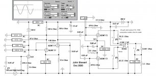
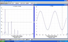
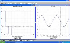
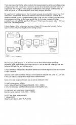
OPT Losses at Clipping
The switch 'A' is used to include the actual copper loses of the OPT, in this case a Hammond 125E. Stuffing the numbers into the HP67 that calcs out to 0.67 db. Anyone out there with bats ears hear that?😀There are iron losses as well but not included here. Transformers are often designed so that at there spec'd operating conditions, core & copper losses are equal.🙂
The switch 'A' is used to include the actual copper loses of the OPT, in this case a Hammond 125E. Stuffing the numbers into the HP67 that calcs out to 0.67 db. Anyone out there with bats ears hear that?😀There are iron losses as well but not included here. Transformers are often designed so that at there spec'd operating conditions, core & copper losses are equal.🙂
Attachments

 done
done Very cool! To think that my little flea amplifier has come all the way to seven ear-shattering watts in the capable hands of one who's posts I always enjoy reading.
We are moving into our new house and I'll finally have a workshop again so hope to get more into working with the flea soon. This is great inspiration!
We are moving into our new house and I'll finally have a workshop again so hope to get more into working with the flea soon. This is great inspiration!
Minor point (nomenclature): your description shows both finals as T2. Unless you run unequal triodes as finals it should probably read T1A and T2A? Any numbers on THD to publish / any FB plans in the cooking?With a pair of 6EA7/6EM7s the waste heat can be shared by two bulbs.
That is a good point. Usually I would identify the tubes as V1A or V2, Etc. But in this case I have identified which triode of each tube is used, following the way in which the two sections of the non-similar triodes are ID in the tube manuals.
So T1 is the lesser high mu triode while T2 is the power triode. That comes from the way they are identified in the tube models in the simulation.🙂
So T1 is the lesser high mu triode while T2 is the power triode. That comes from the way they are identified in the tube models in the simulation.🙂
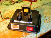
Cleared the workbench yesterday & gutted the Betty Crocker Amp Chassis. The Chassis will be reloaded later today. After the new snow is cleared!
Finally on the Test Bench
And it makes an honest 7W at clipping. At One Watt the D% at 2H is 0.67%. No NFB. More results & traces later.🙂
And it makes an honest 7W at clipping. At One Watt the D% at 2H is 0.67%. No NFB. More results & traces later.🙂
A good point. I will dig that sim out later, something is not correct. Usually an error in a sim causes a flag. Best part of a sim, an error doesn't cause smoke.😀
Small amps with TV dissimilar triodes are just great little amps. I have done myself one with 1 PCC88 and 2x6DR7 per channel. Williamson style, 5W class A, low fbk.
Did you invent a PNP-tube ? 😀
Mona
I found that sim, it still generates that very odd result. I'll dig down into that later when time is available.🙂
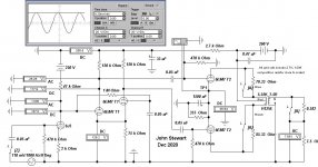
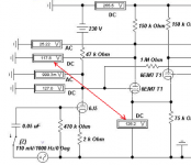
The schematic for the amp in its present form is attached. There are no boutique or special parts, everything is off the shelf.
Attachments

Intermodulation Tests
And for comparison the tests done 2yrs ago on a similar amp using a 5998 twin triode power stage. The IMD tests were done using the SMPTE method, originally a 4:1 signal of 60 Hz (or 50 Hz) & another at 5 to 8 KHz. The LF signal was simply taken from the AC local power, for the method used any D% in the power source had minimal effect.
For these tests the LF signal is obtained from a 2nd audio oscillator. That way any power supply problems shew up separately & easily identified.
The 6EA7 & 6EM7 are essentially the same.🙂
Attachments


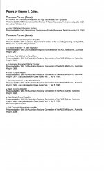
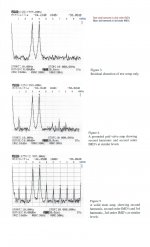
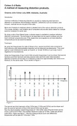
Testing for IMD & THD using the Cohen 3-4 Method
Graeme Cohen devised this very good method of distortion measurement in 2008, it separates the IMD from the THD products in the output of an amplifier. His paper describing the technique is attached.
The PP 6EA7/6EM7 amp is set at 3 watts, about the half power point.
So next time you pick up your favorite Flamenco or Brahms Vinyl you will hear it as recorded along with all the Intermods. And having 300B outputs won't help, aside from reproducing at a level where these problems are minimized.🙂
Attachments
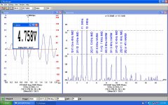
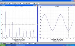
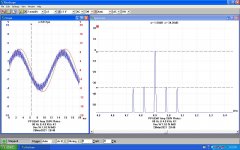
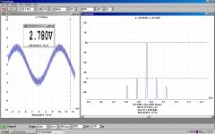
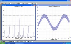
SMPTE Test at ~5 Watts
As can be seen on these first tests the 5KHz component is compressed at top & bottom of the 80 Hz wave. No 60 or 120 Hz sidebands, the PS is regulated. But AC on the heaters.
The first pair of sidebands at +/- 80 Hz measure 4.16% of the 5 KHz. The 2nd pair of sidebands at +/- 160 Hz measure 3.11 %. Doing ROOT of SUM of SQUARES sez the IMD in this test is 7.35 %.
Next week I'll try separate bias resistors & caps on the power triodes, that may improve the IMD numbers.
One of the HK IMD test sets would simplify this. But we would never see the detail as here.
This weekend one of my Grandchildren gets married. No time for electronix.🙂
Attachments

- Home
- Amplifiers
- Tubes / Valves
- On The Back Burner 7 Watt 6EA7 PP Amp