This flipflop uses a feature of the relays:
THE HOLD CURRENT IS MUCH LESS TAN THE PULL-IN CURRENT .
The hysteresis is exploited by this circuit.
Once a relay is energized, it can keep relay actuated even tough
its coil is in serie with the coil of other relay.
The supply voltage is applied to relays coils during pushing the
PB1, when pushbutton is pressed to ON, or to OFF the circuit
(step 1 and step 3). This is an intermediary state of the
circuit, not permanently.
The half of supply voltage is applied on the coils of each
relay in the stable state of the circuit, when the pushbutton
is released and the circuit is in the ON state, and the flipflop
stay in this configuration indefinitely.
During the intermediary state of the circuit, overvoltage is
not dangerous for the life of the relays, if they are corecly
choosen for the electric characteristics point of view.
Hi Roger,
I think what we are being told is that 110Vac relays can be used on 110Vac supply.
One or other relay sees 110Vac when the push-push switch is held in, but then sees just 55Vac when the switch is released. Both relays are in series when the switch is latched on and both relays will run cool.
Is this the correct interpretation?
I hope, the following description and the schematics shown
in attached file toggle2relays_4.png, will help you
to better understand how this flipflop work:
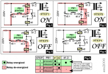
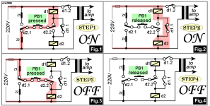
Initial, the circuit is as shown in Figure 4, both relays
are de-energized.
When we press (push) button to START, (Figure 1), relay d1 takes
220V, ONLY DURING THE FINGER IS PUSHING THE BUTTON. This is the step 1.
Current flows through relay d1, contact d2.2, button PB1 and contact d2.1.
During step 1, the coil of d2 is bypassed by d1.1+d2.2+PB1+d2.1; there is
no path for current through relay d2, so relay d2 is not yet energized.
Contact d1.2 turns on the amplifier.
When the pushbutton is released, to continue the starting process, Figure 2,
because realy d1 is energized and contact d1.1 is closed, the opening of the PB1
diverts current through the coil of relay d2 (now, d2 is not bypassed).
Current flows through coil of relay d1, series coil of relay d2 and contact d1.1.
This is the finnish of step 2, the flipflop will stay in this configuration indefinitely.
This is a STABLE STATE OF THE FLIPFLOP, when the amplifier is working.
Now, we want to turn off the amplifier and we actuate the pushbutton again, by pressing it.
Current flows like in Figure 3, through the coil of relay d2.
Relay d2 takes 220V - ONLY WHEN THE FINGER IS PUSHING THE BUTTON. This is the step 3.
Now, the coil of d1 is bypassed by d2.1+PB1+d2.2, there is no path for current through
relay d1, so relay d1 is de-energized, contacts d1.1 and d1.2 now opens.
The amplifier is OFF.
There is not any reason to stay with the finger on the button PB1 anymore, the pushbutton
is released, and current stops flowing through the coil of relay.
We are back to the intitial configuration of figure 4.
This is the finnish of step 4.
The flipflop will stay in this configuration indefinitely.
This is the STABLE STATE OF THE FLIPFLOP, when the amplifier is not powered (OFF).
in attached file toggle2relays_4.png, will help you
to better understand how this flipflop work:
Initial, the circuit is as shown in Figure 4, both relays
are de-energized.
When we press (push) button to START, (Figure 1), relay d1 takes
220V, ONLY DURING THE FINGER IS PUSHING THE BUTTON. This is the step 1.
Current flows through relay d1, contact d2.2, button PB1 and contact d2.1.
During step 1, the coil of d2 is bypassed by d1.1+d2.2+PB1+d2.1; there is
no path for current through relay d2, so relay d2 is not yet energized.
Contact d1.2 turns on the amplifier.
When the pushbutton is released, to continue the starting process, Figure 2,
because realy d1 is energized and contact d1.1 is closed, the opening of the PB1
diverts current through the coil of relay d2 (now, d2 is not bypassed).
Current flows through coil of relay d1, series coil of relay d2 and contact d1.1.
This is the finnish of step 2, the flipflop will stay in this configuration indefinitely.
This is a STABLE STATE OF THE FLIPFLOP, when the amplifier is working.
Now, we want to turn off the amplifier and we actuate the pushbutton again, by pressing it.
Current flows like in Figure 3, through the coil of relay d2.
Relay d2 takes 220V - ONLY WHEN THE FINGER IS PUSHING THE BUTTON. This is the step 3.
Now, the coil of d1 is bypassed by d2.1+PB1+d2.2, there is no path for current through
relay d1, so relay d1 is de-energized, contacts d1.1 and d1.2 now opens.
The amplifier is OFF.
There is not any reason to stay with the finger on the button PB1 anymore, the pushbutton
is released, and current stops flowing through the coil of relay.
We are back to the intitial configuration of figure 4.
This is the finnish of step 4.
The flipflop will stay in this configuration indefinitely.
This is the STABLE STATE OF THE FLIPFLOP, when the amplifier is not powered (OFF).
Attachments
Clever circuit.
Although Z1 and Z2 are probably not needed because the PB1 is only pushed briefly (as EM2006 said), you can still avoid this short coil overload by using only a single resistor instead of Z1 and Z2. Just put a single Z in series with PB1, than it will act in both 'Pressed' conditions of Fig 1 and Fig 3.
Steven
I never tested this circuit using AC relays, but I 've tested it with many types of DC relays.
DC relays have the advantage that allowed permanent voltage higher than rated voltage.
For example, many types of DC relays allow power DC coil with a permanent voltage 1.8 times higher than rated voltage, so overvoltage is not dangerous.
Exploiting hysteresis, on-off circuit using a single DC relay can be done.
http://www.edn.com/archives/1997/050897/10di_02.htm
- Status
- This old topic is closed. If you want to reopen this topic, contact a moderator using the "Report Post" button.
- Home
- Amplifiers
- Solid State
- On/Off Switch