Not quite correct - the voltage across a single Re will fall to ~0V as the output stage enters Class B. What needs to be detected is the minimum voltage across both Re which will give a voltage that is twice the quiescent voltage for a single Re.The voltage across an Re in AB is half-sines (assuming sine signal) on top of a DC level from Ibias. Detect the minimum of that waveform and you can use that to control Ibias via feedback.

Last edited:
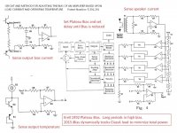
Between 1992 and 2014 Krell used a Plateau Bias described in Patent Number: 5,331,291. Based upon sensed output bias voltage .AND. output transistor temperatures .AND. current driven into the speaker load, a microprocessor set a modestly higher than required output bias to maintain ClassA operation, up to the maximum safe limit, for a long time period even after the transient power demands dropped. Stable, high ClassA operation at a uniform transistor temperature for a modest period after the power demands drop.
Krell's patent pending 2014 iBias scheme uses dynamic tracking sensors to set ClassA bias for only as long as required. iBias allows Krell to significantly reduce both physical size and fan cooling demands for HT rack mounting.
Krell's patent pending 2014 iBias scheme uses dynamic tracking sensors to set ClassA bias for only as long as required. iBias allows Krell to significantly reduce both physical size and fan cooling demands for HT rack mounting.
Attachments
Not quite correct - the voltage across a single Re will fall to ~0V as the output stage enters Class B. What needs to be detected is the minimum voltage across both Re which will give a voltage that is twice the quiescent voltage for a single Re.
Yes I agree.
Jan
I think there is a flaw in the philosophy.Between 1992 and 2014 Krell used a Plateau Bias described in Patent Number: 5,331,291. Based upon sensed output bias voltage .AND. output transistor temperatures .AND. current driven into the speaker load, a microprocessor set a modestly higher than required output bias to maintain ClassA operation, up to the maximum safe limit, for a long time period even after the transient power demands dropped. Stable, high ClassA operation at a uniform transistor temperature for a modest period after the power demands drop.
Krell's patent pending 2014 iBias scheme uses dynamic tracking sensors to set ClassA bias for only as long as required. iBias allows Krell to significantly reduce both physical size and fan cooling demands for HT rack mounting.
The output offset will change as the bias is increased. The speaker will read this change in offset as part of the audio signal.
If the return to low bias is slow, then the speaker cannot respond to the slow return to near zero output offset.
I have never seen any comment that offset is corrected, by any of these active bias control circuits, as the bias is changed.
I see that Vab is decidedly asymmetrical.Not quite correct - the voltage across a single Re will fall to ~0V as the output stage enters Class B. What needs to be detected is the minimum voltage across both Re which will give a voltage that is twice the quiescent voltage for a single Re.
Is this the crossover distortion?
or is it just a high 2nd harmonic + others?
I think there is a flaw in the philosophy.
The output offset will change as the bias is increased. The speaker will read this change in offset as part of the audio signal.
If the return to low bias is slow, then the speaker cannot respond to the slow return to near zero output offset.
I have never seen any comment that offset is corrected, by any of these active bias control circuits, as the bias is changed.
Andrew why would the offset change with bias?? That's new to me.
New to my amps, too ;-)
Jan
I have tried it.
The slight imbalance in the P & N devices require the output offset to be corrected when the output bias current is changed.
I have measured this many times on many quite different implementations.
The slight imbalance in the P & N devices require the output offset to be corrected when the output bias current is changed.
I have measured this many times on many quite different implementations.
I have tried it.
The slight imbalance in the P & N devices require the output offset to be corrected when the output bias current is changed.
I have measured this many times on many quite different implementations.
I don't agree Andrew. I have NEVER seen it. Unless you have an amp that has DC gain, no servo and a trimpot for offset, there you may see it, but I hope we would have left such crummy designs behind us a few decades now ;-)
I actually have a pair of vintage Sony TA-N68 power amps that can be switched from A to AB (switching bias and power rail). There's absolutely no change in offset, but of course this has a servo.
Jan
Last edited:
- Status
- Not open for further replies.
- Home
- Amplifiers
- Solid State
- Oliver Offset Optimiser