rickl said:
I even use ---------- ear muffs for some suspect gear.
rick
Ahha'... I detect someone who is scary of a good bang ?
Eyes are more important. Watchout with TO220/larger plastic packages with a suspect psu... these devices behave as small handgranades when exploded..... the bang isn't signifigant but the fragments can damage eyes.
Actually listening carefully on warm up can reveal alot of duff components and misbehaviour. For example a full bridge rect gone half wave can make a mains transformer throb esp when a variac is used.
richj
Questions
Could someone please answer the following questions asked in post #
13. I may need to get and install parts.
1.Am I correct in assuming that the " coupling capacitors", for the 500C, are the four .047 's, 2 per side, which connect a pin on each of the 7591's and the 12AX7's?
2.All are W. German and have a black band on the ends closest to the 7591's. Is that the + end?.
tomtt
I shotsome pics this morning. I will see if I can manage to post the one with, what I believe are, the coupling caps.
Thanks to All, Vic
Hi Victoria,
The 0.047's sound like the coupling caps to the output tubes, there are others. Anything in that package is likely a coupling capacitor.
The band indicates the lead connected to the outer foil. These capacitors should not be polarized.
Happy hunting Victoria! (I like your full name) 😉
-Chris
The 0.047's sound like the coupling caps to the output tubes, there are others. Anything in that package is likely a coupling capacitor.
The band indicates the lead connected to the outer foil. These capacitors should not be polarized.
Happy hunting Victoria! (I like your full name) 😉
-Chris
Some Progress!!!
Thanks guys, you made my day!!! Yesterday was my 75th birtday and you made it FUN!!
The big brown truck brought the variac yesterday AM. I hook up the Fisher 500C and took about 5 hours to get to line voltage. Nothing blew up, No tubes flashed or glowed like light bulbs!! But no sound.
This morning I let it idle at 70V for a couple of hours, wiggled the tubes, and now I have *very* low sound in both channels. Also static when using the the volume or mode switch.
I probably ought to clean all the switches. Is deOxit the stuff to use? If the low level sound persists,
what would you suggest next?
Anatech
The "Victoria" is a result of being told I couldn't use "Vic" when I registered for these forums.
Thanks, Vic
Hi Vic,
Yes, DeOxId is the correct stuff, whether it's Caig or GC. If you still have a bottle of the red "Quietrol", that would work also.
Low sound could be a leaky coupling cap or low B+, check the voltage readings. You may have an entire set of weak output tubes. Test them (all of them, why not?)
-Chris
Yes, DeOxId is the correct stuff, whether it's Caig or GC. If you still have a bottle of the red "Quietrol", that would work also.
Low sound could be a leaky coupling cap or low B+, check the voltage readings. You may have an entire set of weak output tubes. Test them (all of them, why not?)
-Chris
Vic,
Congrats on 75 years! I don't have expectations of getting there myself. Question. Why did you wait so long to try to appreciate these tubed gems?
Congrats on 75 years! I don't have expectations of getting there myself. Question. Why did you wait so long to try to appreciate these tubed gems?
Checking B+
Anatech
Can you tell me how to do this or point me to an online explanation? I do have an old US Military book called "Basic Theory and Application of Electron Tubes" Feb 1952. Cathode Bias is one of the things discussed, is that what you are talking about? I also have a schematic for this unit. Like I said earlier, I am not the second coming of Tesla (but I did write my thesis on his turbine in 1960), and I have little past experience with electronic gear. I have a Fluke 8012A Digital Multimeter. Is that adequate?
As any aside, my Mother was born in the Stratford/Kitchener area.
Thanks, Vic
Hi Vic,
Your meter is fine for this. Do you have an oscilloscope? It's good for checking ripple on supplies.
Your book, Basic Theory and Application of Electron Tubes, should be able to give you the basics. You want to make sure all your B+ voltages are in the ballpark from the rectifier back. Very warm filter caps are not a great sign of health, they will get slightly warm. Measure the B+ voltages (be careful please!) and write them down. I may have the schematic, I'm sure others can help too.
Kitchener is not that far from here! They still build great furnature there.
-Chris
Fisher 500c Schematic
I have a schematic of the 500C but it is 633k. Too big to post. I can email it if you want it.
rick
I have a schematic of the 500C but it is 633k. Too big to post. I can email it if you want it.
rick
Hi Rick,
The one I have is smaller. Yours might be a higher res.(cool) 😎 So please send it.
bhome at sympatico dot ca
And many thanks!
-Chris
The one I have is smaller. Yours might be a higher res.(cool) 😎 So please send it.
bhome at sympatico dot ca
And many thanks!
-Chris
I can still barely get FM stereo audio outout at full volume--barely hear it.
After looking at the bases of the three multi cap cans, it would appear that they never have been changed. (Probably also true of the coupling caps and the selenium rectifier).
So I have two more questions:
(1)Could a problem with any of these lead to the current situation? and
(2)Is there a way to check them to see if they are in bad?
Thanks again, Vic
Hey Vic,
Selenium rectifiers are just problems waiting to happen, if they already haven't gone defective.
What circuit is it in? If bias, just use 1N4006 or 1N4007 (I just buy 1N4007's, they are about the same price as the lowest ones). If they are for heaters, figure out what the current draw is and use a resistor to drop some voltage. They did this in my 400C control amp.
Don't check, just change. They will get you if you leave them in.
-Chris
Victoria said:
So I have two more questions:
(1)Could a problem with any of these lead to the current situation? and
(2)Is there a way to check them to see if they are in bad?
Thanks again, Vic
Get a schematic and start checking voltages at the pins. I know when I was debugging my Fisher tuner I just started checking and comparing with what was listed on the schematic. The problem I had was the final 'rootbeer barrel' caps were leaky and passing DC.
I wouldn't replace the PS cans until you know they are bad. Weak output isn't a ps problem. Hum, yes but not low output.
BTW, I have never seen a 500C let alone worked on one so there maybe something I'm missing.
Fisher 500C Schematic
rick
anatech said:Hey Vic,
Selenium rectifiers are just problems waiting to happen, if they already haven't gone defective.
What circuit is it in? If bias, just use 1N4006 or 1N4007 (I just buy 1N4007's, they are about the same price as the lowest ones). If they are for heaters, figure out what the current draw is and use a resistor to drop some voltage. They did this in my 400C control amp.
Don't check, just change. They will get you if you leave them in.
-Chris
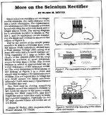
Hi, I'm in the process of fixing a HP 410B that I got for nothing and one of the things everyone was saying is 'get rid of the selenium rectifier' I found a good article from Antique Radio that suggests replacing the selenium rec w/ just as you mentioned a 1N4007 and add a 2 ohm resistor in series with it to compensate for the added efficiency of the silicon diode. A small terminal strip will make thing easier. Another recomendation was to get rid of the Black Beauty caps as well. Sorry for the bad scan but maybe it will help.
Stan
Attachments
Hey Stan,
You're a lucky fella. HP stuff is great!
The scan is rough, but it illustrates things well.
Sometimes you need to play with the resistor value to get the expected voltage right. That is the correct idea, and yes, I try to use terminal strips as the dropping resistor can get warm.
-Chris
You're a lucky fella. HP stuff is great!
The scan is rough, but it illustrates things well.
Sometimes you need to play with the resistor value to get the expected voltage right. That is the correct idea, and yes, I try to use terminal strips as the dropping resistor can get warm.
-Chris
Tube Condition
I have temporarily set the 500C aside and am currently looking at the Dynaco ST-70. But the very top of the 5AR4 tube is milky colored, not silver. Is that an indication that I shouldn't go any farther before I replace it. Or is that normal and I should proceed. I don't have a tube tester. Thanks, Vic
I have temporarily set the 500C aside and am currently looking at the Dynaco ST-70. But the very top of the 5AR4 tube is milky colored, not silver. Is that an indication that I shouldn't go any farther before I replace it. Or is that normal and I should proceed. I don't have a tube tester. Thanks, Vic
Hey Vic,
The vacuum is gone in that tube. Careful as the glass may cut your hand if you pull it. Handle by the base only.
-Chris
The vacuum is gone in that tube. Careful as the glass may cut your hand if you pull it. Handle by the base only.
-Chris
david hafler remains a hero(rhymes with keros) for
many pepole however,
the transformers in the sansui are of much better quality
http://www.tube-amps.net/index.htm
many pepole however,
the transformers in the sansui are of much better quality
http://www.tube-amps.net/index.htm
Anatech
Thanks for the info and the alert!
tomtt,
I hear you and appreciate your help. I read about Hasimoto after your first comment about the 1000A. Is the site you linked to yours?
Thanks again guys, Vic
Thanks for the info and the alert!
tomtt,
I hear you and appreciate your help. I read about Hasimoto after your first comment about the 1000A. Is the site you linked to yours?
Thanks again guys, Vic

- Status
- Not open for further replies.
- Home
- Amplifiers
- Tubes / Valves
- Old Tube Equipment Turnon