Hi adamus,
Sorry for my ignrance, did you use the DAC END2 H/V power supply for the CSS?
Thanks
Sorry for my ignrance, did you use the DAC END2 H/V power supply for the CSS?
Thanks
yes, but B+ dropping resistors are needed or the CCS is too hot. 4k7 drop resistors per tube, pull the 47k resistors and replace with a CCS, i used the dn2450n5 cascode
I think the project goes far beyond my knowledge to make this DAC sing.
I guess that I will put it on sale, boards, chips, Jensen cap, OSCONS and Kinawe resistors that have already in hand. If someone is interested, please pm me.
I guess that I will put it on sale, boards, chips, Jensen cap, OSCONS and Kinawe resistors that have already in hand. If someone is interested, please pm me.
I have the exact same "problem". With DAC-board attached I get zero vgs on the last mosfet and about 5.16-5.18V before the TL431.
This is without the CS8414 and AD1865 installed.
As soon as I find some time I'll try as Adamus to parallel a 27r with Rset
Your DAC , it work?? what is the happen?
Everything is finished, but I'm still waiting for a new CS8414.
I think it died during my attempts to solder it to the converter PCB.
But I have measured everthing twice to make sure everything is in working order before the new CS part gets here. And it seems I have some work to do on the Salas psu..
I think it died during my attempts to solder it to the converter PCB.
But I have measured everthing twice to make sure everything is in working order before the new CS part gets here. And it seems I have some work to do on the Salas psu..
Hey Tassosk,
Don't be discourage. I'm on the same boat as you. Just keep on going and this is what DIY for.🙂
Don't be discourage. I'm on the same boat as you. Just keep on going and this is what DIY for.🙂
same for me if you read back, infact exactly the same on the 5+v dig.
At 'max' the salas board is not regulating, the final mosfet isnt doing anything. its not ideal, but increase parallel another 27r with the rset resistors which will increase the 5.19 to 5.3 ish... then back off a little to ensure regulation. The tl431 doesnt need much headroom unless my scope is lying.
Salas, i had a play with the dig line. when the shunt reg 'maxes out' the vgs goes to zero on the final mosfet. back off a little and it comes up to 4v or there abouts. any ideas?
I noticed that as the end mosfet doesn't even get warm. Stays dead cold.
However the -ve 5 analog one does get warm...
So where do i need to put a 27 resistor?
Parallel to r14 and r2?
Hey Tassosk,
Don't be discourage. I'm on the same boat as you. Just keep on going and this is what DIY for.🙂

Thanks for the kind words fredlock 🙂
R13 and R1 then?
Ok after some looking into I have 0.02v across the drain and source of the second fet in the digi 5v.
I get 3.7v ish across the other "seconds". I.E number 2 of 5v analog and -5v analog.
After more investigation as soon as i drop +5v digi to 5.15 or less i get 3.6ish across the second fet...
Am i better running it like this?
Last edited:
I tried parallel a 10r resistor with the R13 and could adjust up to 5.50V without Q16 Vgs dropping below 3.80V.. Great! But now Q13 got really hot instead :/ Guess I have to change the 10r to something with higher r.. Or add a bigger sink on Q13..
Thanks guys for sharing.
Thanks guys for sharing.
10r with 27r is not a lot of R, so the mosfet will get hot. try parallel a 27r or 20r.
Yes, I will try that. Good thing is that it now seem to work as intended. 🙂
I tried parallel a 10r resistor with the R13 and could adjust up to 5.50V without Q16 Vgs dropping below 3.80V.. Great! But now Q13 got really hot instead :/ Guess I have to change the 10r to something with higher r.. Or add a bigger sink on Q13..
Thanks guys for sharing.
you can use 2 x 33R parallel. So need heansick for Q13, it is hotter!
Ok, i just dropped in another 27k into r13 and now its at 5.22v max.
Isn't that still low?
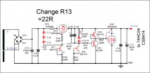
27R nor 27K, It is ok, so better You can change R 13 = 22R.
Sorry i meant 27r...So now i have 2 27r's in parallel giving me ~13r.
Just a single 22r is what you advise quanghao?
Just a single 22r is what you advise quanghao?
Sorry i meant 27r...
Just a single 22r is what you advise quanghao?
yes! 22R, See it please!
Attachments
Last edited:
- Status
- Not open for further replies.
- Home
- More Vendors...
- Quanghao Audio Design
- OLD THREAD DAC End by Andrea Ciuffoli