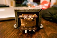
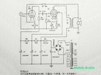
I am looking for output transformers for simple SE amp. The schematics wants 5K tranny. I have a pair of old transformers taken from stereo radio(made 1950's) and I wonder if I can use these. How to find out?
Primary(lower coil) is the thicker wire with center tap.
Primary(lower coil) is the thicker wire with center tap.
Attachments
Last edited:
The primary for SE OPT should not have a CT and usually is the thinner wire with respect to secondary.
Assume you have no taps, just primary and secondary.
Feed 1 kHz signal from function generator etc. (few volts min.) and measure the voltage at the secondary.
Calculate the voltage ratio (Upri / Usec). This is the "turns ratio", also called voltage transforming ratio.
The impedance transforming ratio is (turns ratio) x (turns ratio).
If you want to know what load impedance 8 ohms at the secondary will create, just calculate: (turns ratio) x (turns ratio) x 8 ohms.
Then measure the inductance of the primary to see it has sufficient reactance to cover the 5k where you need it.
I forgot to mention that the radio the transformers were taken from was SE parallel 2*EL84(4 EL84 total). One of the first stereo radios made in Sweden.
An SE OPT from an old radio may have a primary tap, although it may not be at the centre of the winding. This, if present, is probably for ripple reduction.
A very quick answer is that an SE OPT can almost certainly be used again for a similar size valve running from a similar voltage rail to the original radio. Impedances don't have to be exact. If you wanted really high quality sound then you would not be using SE and you would not be using OPTs from old radios.
A slightly slower answer is that the impedance ratio of an OPT is likely to be not too different from the resistance ratio of the windings - at least to within a factor of about 2 either way.
For the official answer see posts 3 and 4.
The OPT looked kind of small for a parallel EL84 SE amp. Based on PSE EL84, I would just assume it is 3K and move forward to bread board it (to see if the OPTs are good enough).
I am looking for output transformers for simple SE amp. The schematics wants 5K tranny. I have a pair of old transformers taken from stereo radio(made 1950's) and I wonder if I can use these. How to find out?
Primary(lower coil) is the thicker wire with center tap.
Are there any wires coming out the other side? If there are the appearance is a lot like a Hammond 125D. That would have been in a PP amp, next to no gap.🙂
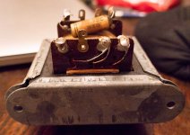
Looking at those photos again, the OPT has 8 soldering lugs. The Hammond 125 Series PP OPTs have only six. So not a Hammond 125D.🙂
First thing is, as has been said before, the thick wires are the secondary. The thin wires are the primary. It is common practice to have a small value capacitor across the primary in old radios to stop too much HF output above 9kHz, before FM. The secondary tap could just be for cathode feedback, Philips and Grundig (+ others) had some odd circuit designs!
Again most old European radios had 3 or 4 ohm speakers.
Second, again said before, that is a very small core for parallel EL84s? And it has to be single ended as there is only one primary... Can you see the air gap in the laminations?
If you know the Make and model the transformers came from it would help you a lot.
In AC/DC radios the tap is usually at about 3% from the B+ end. The tap goes to B+, the short wdg end to the screen cct & the rest of the front end, the plate to the long wdg. That way ripple in the PS is reduced in the plate current of the output tube plate, the screen sees the opposite phase. Usually found in low cost AM radios.🙂
Suppression of the IF freq left in the audio after detection is primarily suppressed by the RC filter network at the top of the gain control. Not often, some designs include a cap across the OP Tube plate cct. Trying to get a balance between the hi freq & lo freq audio in a radio with a small speaker. That is covered very well in the Radiotron Designers Handbook 4 (RDH4.)
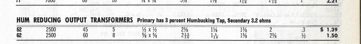
The OPT examples in the attachment copied from the Hammond 1960 catalogue,
Suppression of the IF freq left in the audio after detection is primarily suppressed by the RC filter network at the top of the gain control. Not often, some designs include a cap across the OP Tube plate cct. Trying to get a balance between the hi freq & lo freq audio in a radio with a small speaker. That is covered very well in the Radiotron Designers Handbook 4 (RDH4.)
The OPT examples in the attachment copied from the Hammond 1960 catalogue,
Attachments
. If you wanted really high quality sound then you would not be using SE and you would not be using OPTs from old radios.
mmm… couldn't have said that better, myself.
Oddly enough, from what I've found so far, there wasn't really very much "wrong" about the design of older transformers except that the designers of radios were almost slavishly compelled to reduce costs. Use cheaper tubes, use cheaper resistors, cheaper capacitors, cheaper transformers, everything .. cheaper.
One (to me infamous) fellow was renowned for clipping parts out of televisions "from the competition" to see if the part was really necessary. When the fewest parts were left, then he'd substitute cheaper parts, lower value caps, and so on until again, the device wasn't working. Several weeks later, an absolute barely-acceptable minimum was achieved. Copy that, and you've got a lower-cost competitor in the otherwise uncritical public market.
So likely is that the recycled output transformer is significantly underwhelming in specification. Insufficient core material for more than a few watts of output. Insufficient copper to provide the kind of high-inductance high-reactance primary that is now given to be optimal — and standard — for true Hi Fi.
Other than that… fine!
Just saying,
GoatGuy
PS: the poster that suggested putting 1 volt of 1 kHz on either the primary or the secondary, and seeing what the response is of the “other side” is right on the money.
Measuring the inductance of the primary tho', without an LCR meter, is hard. You can do it with the signal generator, but it is a pain, since it also requires the signal generator to have enough output oomph to drive real current thru the primary … at 1 kHz. But, for instance:
So for an example of L = 10 henries, F = 1,000 Hz
The fairly straight forward way to measure this is to put the primary in series with a 1000 Ω resistor. Use the 1 kHz. Measure the voltage across the resistor (using an oscilloscope, since it'll be small), and likewise across the primary.
Whatever the ratio is, then gives Z at 1 kHz. Say the voltage VR = 0.08 volts, and that across the primary is VP = 0.92 volts.
While it might seem ideal to choose a resistor high enough so that the primary and the resistor are "fairly sharing" the voltage division, this turns out to be a bad idea. The choke or coil or transformer winding needs to have almost all of the voltage. The problem relates to the current-lag of chokes compared to resistors.
Anyway… if you don't have an oscilloscope or signal generator, then working with A/C (from another well known transformer) isn't a bad option. Your frequency is on the low side (50 or 60 Hz), but you've got a source of voltage which an el-cheapo multimeter can measure to 3½ significant digits. Different resistor required. 100 Ω, or thereabouts.
Just saying,
GoatGuy
Measuring the inductance of the primary tho', without an LCR meter, is hard. You can do it with the signal generator, but it is a pain, since it also requires the signal generator to have enough output oomph to drive real current thru the primary … at 1 kHz. But, for instance:
Z = 2πFL
So for an example of L = 10 henries, F = 1,000 Hz
Z = 6.28 × 1000 × 10
Z = 62.8 kΩ
Z = 62.8 kΩ
The fairly straight forward way to measure this is to put the primary in series with a 1000 Ω resistor. Use the 1 kHz. Measure the voltage across the resistor (using an oscilloscope, since it'll be small), and likewise across the primary.
Whatever the ratio is, then gives Z at 1 kHz. Say the voltage VR = 0.08 volts, and that across the primary is VP = 0.92 volts.
ZP = R × 0.92 ÷ 0.08
ZP = 1000 × 11.5
ZP = 11.5 kΩ. at 1,000 Hz…
11500 = 2πFL
L = 11500 Ω / (6.28 × 1,000 Hz)
L = 1.83 henry
ZP = 1000 × 11.5
ZP = 11.5 kΩ. at 1,000 Hz…
11500 = 2πFL
L = 11500 Ω / (6.28 × 1,000 Hz)
L = 1.83 henry
While it might seem ideal to choose a resistor high enough so that the primary and the resistor are "fairly sharing" the voltage division, this turns out to be a bad idea. The choke or coil or transformer winding needs to have almost all of the voltage. The problem relates to the current-lag of chokes compared to resistors.
Anyway… if you don't have an oscilloscope or signal generator, then working with A/C (from another well known transformer) isn't a bad option. Your frequency is on the low side (50 or 60 Hz), but you've got a source of voltage which an el-cheapo multimeter can measure to 3½ significant digits. Different resistor required. 100 Ω, or thereabouts.
Just saying,
GoatGuy
An OPT from an old radio is unlikely to have enough inductance to go really low in frequency - no point when the speakers and cabinet could not. In fact it is best if the OPT cannot go too low.
Similarly, it is unlikely to be carefully wound in sections to reduce capacitance and raise the HF resonance, as probably not much feedback would have been used. Typically no feedback at all.
All the OPT had to do was make a pleasant sound from maybe 100Hz to 5-8kHz. Better radios would be a bit better than this, cheaper ones a lot worse.
- Status
- Not open for further replies.
- Home
- Amplifiers
- Tubes / Valves
- Old SE transformer - how to determine load resistance.