I have used wood as a building platform since I began building electronic circuits many years ago. It has always been and still is my favorite "media" for prototyping audio circuitry.
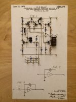
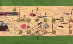
This photo is my latest circuit "board". It is an old circuit that (I believe) may be one of the first examples of the summing amplifier that is commonplace today in op amp designs. Back in 1968 it was unique enough to be granted a patent. I built the breadboard to be able to play around with the design to see what I could learn from it.
The board was built on cabinet grade plywood. I attach a copy of the schematic diagram printed to size to the plywood with "glue stick" adhesive. This works well since it is low moisture and doesn't wrinkle the paper. Then brass escutcheon brads are nailed into the wood at connection points for the circuit. Once the brads are in place (with about a half inch exposed) I wire the circuit using plated solid copper buss wire soldered to the brads. The brass solders easily. Once wiring is in place the components are soldered in.
Breadboards made this way are easy to experiment with. They can be made large enough to make trying different components an easy task. And they survive revisions very well.
Attachments
Last edited:
I was brought up on strip board for prototypes.
It usually works ok.
I have had circuits fail and blow off the strip board tracks.
These days I usually go straight to pcb's from China.
It China pcbs cost 1/3 the price of what they do in the UK.
Obviously you need to get the circuit right if you go straight to pcb.
I sometimes knock up parts of the circuit I am unsure about on strip board before going to pcb.
I have used wood as a building platform since I began building electronic circuits many years ago. It has always been and still is my favorite "media" for prototyping audio circuitry.
This photo is my latest circuit "board". It is an old circuit that (I believe) may be one of the first examples of the summing amplifier that is commonplace today in op amp designs. Back in 1968 it was unique enough to be granted a patent. I built the breadboard to be able to play around with the design to see what I could learn from it.
The board was built on cabinet grade plywood. I attach a copy of the schematic diagram printed to size to the plywood with "glue stick" adhesive. This works well since it is low moisture and doesn't wrinkle the paper. Then brass escutcheon brads are nailed into the wood at connection points for the circuit. Once the brads are in place (with about a half inch exposed) I wire the circuit using plated solid copper buss wire soldered to the brads. The brass solders easily. Once wiring is in place the components are soldered in.
Breadboards made this way are easy to experiment with. They can be made large enough to make trying different components an easy task. And they survive revisions very well.
Hello mikegranger. I looked up your patent at United States Patent and Trademark Office. This is an interesting and practical approach to prototyping; highly worthy of adoption. Did you make money of your invention during the time OP amps [like uA709 and uA741] and their virtual ground applications may have competed with [or infringed on] your circuits?
Best regards
Patent was not mine
Antoniel,
The circuit I used to illustrate my wood prototyping does not belong to me. I built it to experiment with it to see what I could learn from its operation.
As you may have noticed the patent literature shows William Dilley as the inventor. He was a well respected designer of professional audio equipment used in studio And broadcasting. Your question is one that I have wondered myself. Thanks for your interest!
Hello mikegranger. I looked up your patent at United States Patent and Trademark Office. This is an interesting and practical approach to prototyping; highly worthy of adoption. Did you make money of your invention during the time OP amps [like uA709 and uA741] and their virtual ground applications may have competed with [or infringed on] your circuits?
Best regards
Antoniel,
The circuit I used to illustrate my wood prototyping does not belong to me. I built it to experiment with it to see what I could learn from its operation.
As you may have noticed the patent literature shows William Dilley as the inventor. He was a well respected designer of professional audio equipment used in studio And broadcasting. Your question is one that I have wondered myself. Thanks for your interest!
Fwiw I think this is really cool... Reminds me a little of a project that got me started in electronics
Kasey197....
Your very cool circuit "board" brings back so many good memories. My first electronics endeavors were all radio related. I can' tell you how many I built before I got a project to actually work! I wish I still had some of those old projects.... I might know enough now to make them work! Thanks for sharing your circuit board with us. Am I right in thinking it is a two transistor AM receiver? What kind of transistors did you use?
Yes indeed that is was what it was. This was from a Ladybird book from the 70's popular in the GB and the commonwealth countries.
IIRC it used the mullard OC series germanium transistors that you could scrape the paint off and make a photosensitive transistor. At some point I could not find them anymore and was advised to use a metal can AC XXX can't recall which ones.
Somewhere on the web is an article describing this particular 'project' along with some improvements necessary for it to work reliably - it never did to my recollection !
The book is called Building a Transistor Radio.
Thank you for the information. I will look around and see if I can find the book or the web site you mentioned. By the way, it has occurred to me recently that most of the projects I built back in the early days were class A biased circuits. They sounded good and I never realized why!Yes indeed that is was what it was. This was from a Ladybird book from the 70's popular in the GB and the commonwealth countries.
IIRC it used the mullard OC series germanium transistors that you could scrape the paint off and make a photosensitive transistor. At some point I could not find them anymore and was advised to use a metal can AC XXX can't recall which ones.
Somewhere on the web is an article describing this particular 'project' along with some improvements necessary for it to work reliably - it never did to my recollection !
The book is called Building a Transistor Radio.
Kasey197:
I took A look around and found this:
MDS975 - "Making A Transistor Radio" by George Dobbs
It obtains the reprint of the book you mentioned as well as construction details to build the radio using the construction technique you used. Very nice. I appreciate your letting us know about this little gem.
")
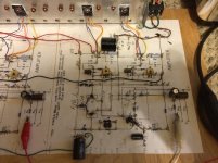
I just finished my latest breadboard project. A while back I was looking at some of Papa's publications and decided to re-read the one about his PLH redesign of the John Lindsay Hood JLH amplifier. My original intent was to construct a stereo pair of the JLH amps to listen to, but having recently built the preamp circuit that started this thread to experience firsthand, I came up with a better idea. Why not try to combine some of the things I learned from studying Papa's designs with the sixties vintage preamp circuit in an attempt to make something both new and old...So I used the Preamp for the front end and a couple of IRFP240's in a totem pole arangement similar to Papa's PLH output stage replacing the preamp's original bipolar output stage. I was pleased and surprised when the circuit actually worked! Attached are a couple of photos of it in operation.
Attachments
Last edited:
Yero
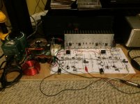
I spent about six hours listening to the stereo power amp circuit Last night. It showed no sign of instability or noise/hum pickup just sitting on my floor. I put a pretty substantial chunk of sheet copper on the ground of the power supply and ran all power and signal ground connections to that star point. The circuit is flat response out to 100 k. I suppose some circuits would not like being built this way but I have not run into that. Making the circuit smaller would be a little harder but not impossible. Give it a try on one of Papa's simple designs. I'll bet you get great results!
I spent about six hours listening to the stereo power amp circuit Last night. It showed no sign of instability or noise/hum pickup just sitting on my floor. I put a pretty substantial chunk of sheet copper on the ground of the power supply and ran all power and signal ground connections to that star point. The circuit is flat response out to 100 k. I suppose some circuits would not like being built this way but I have not run into that. Making the circuit smaller would be a little harder but not impossible. Give it a try on one of Papa's simple designs. I'll bet you get great results!
Yero
I spent about six hours listening to the stereo power amp circuit Last night. It showed no sign of instability or noise/hum pickup just sitting on my floor. I put a pretty substantial chunk of sheet copper on the ground of the power supply and ran all power and signal ground connections to that star point. The circuit is flat response out to 100 k. I suppose some circuits would not like being built this way but I have not run into that. Making the circuit smaller would be a little harder but not impossible. Give it a try on one of Papa's simple designs. I'll bet you get great results!
Is this circuit construction method used just for prototyping or if configured on a smaller scale be a permanent construction method. Is there hum problems due to the absence of a ground plane?
In the past we used a plain phenolic breadboard with a 0.1" grid of hole and did much the same construction. It works pretty well with proper attention to the layout. Keep loops small, and high impedance nodes tight.
rayma, Plain phenolic breadboard with holes, I have not seen this type of board. Do you mean strip board?
It's just plain 1/16" thick phenolic or fiberglass with no copper, and a grid of small holes all over the surface. Here's a sample:
22-516: GC ELECTRONICS: Electronic Design
- Status
- This old topic is closed. If you want to reopen this topic, contact a moderator using the "Report Post" button.
- Home
- Amplifiers
- Pass Labs
- Old School Prototyping