Dear all,
First, thanks a lot for the amazing forum, I have already stolen lots of ideas here... Great job!
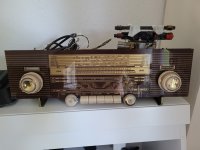
Some time ago I bought an old tube radio thinking it wouldn't work, a Schaub-Lorenz Goldy20, with the idea of building a guitar amp but... it works!! I think it is a pity to destroy it to make a guitar amp, the FM side sounds great (even though should be better for winter due to that temperature XD), but maybe some refurbishing could do?
It actually has an external input so, by selecting LW+MW it does in fact connect the external input to the EABC80 as pre-amplifier, and then the EL84 (I think).
I made a modification in the cathode of the triode of the EABC80, by placing a 10K pot in series of the cathode to ground, and in parallel to the pot a 22nF cap. The idea is to get some overdriven sound by increasing the gain of the EABC80 (positive grid excursions? Like a variable bias cathode resistor if it makes sense).
It actually kind of work, since when it is in FM mode, and minimum volume, rising the resistance of the 10Kpot, the volume rises until it starts to sound distorted. The point is that, when it is in TA mode (by pressing LW+MW switches) it does nothing.
I don't know if:
I post also the schematic with the modification I made. To follow the schematics, the switches labelled L and M in the schema represent the LW and MW switches, needed to select the external output. The position in the schematic show when the selector switch is not pressed.
I would appreciate any help to avoid destroying the radio and still add the guitar amp functionality.
Thanks in advance.
Cheers!
José I.
First, thanks a lot for the amazing forum, I have already stolen lots of ideas here... Great job!
Some time ago I bought an old tube radio thinking it wouldn't work, a Schaub-Lorenz Goldy20, with the idea of building a guitar amp but... it works!! I think it is a pity to destroy it to make a guitar amp, the FM side sounds great (even though should be better for winter due to that temperature XD), but maybe some refurbishing could do?
It actually has an external input so, by selecting LW+MW it does in fact connect the external input to the EABC80 as pre-amplifier, and then the EL84 (I think).
I made a modification in the cathode of the triode of the EABC80, by placing a 10K pot in series of the cathode to ground, and in parallel to the pot a 22nF cap. The idea is to get some overdriven sound by increasing the gain of the EABC80 (positive grid excursions? Like a variable bias cathode resistor if it makes sense).
It actually kind of work, since when it is in FM mode, and minimum volume, rising the resistance of the 10Kpot, the volume rises until it starts to sound distorted. The point is that, when it is in TA mode (by pressing LW+MW switches) it does nothing.
I don't know if:
- The external input doesn't even use the EABC80?
- The AVC (automatic volume control) is cancelling this increase of gain?
- Something I can't even imagine...
I post also the schematic with the modification I made. To follow the schematics, the switches labelled L and M in the schema represent the LW and MW switches, needed to select the external output. The position in the schematic show when the selector switch is not pressed.
I would appreciate any help to avoid destroying the radio and still add the guitar amp functionality.
Thanks in advance.
Cheers!
José I.
Attachments
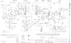
Check contact sets 19-20-21 behind the M switch and sets 4-5-6 behind the L switch. Is there a valid connection between the ext. input terminal and capacitor C110/10 nF if both switches are depressed?
Btw, your modification surely doesn't increase gain. It increases the negative grid voltage of the EABC80 triode, hence reducing plate current, gain and headroom, which itself increases distortion.
Best regards!
Btw, your modification surely doesn't increase gain. It increases the negative grid voltage of the EABC80 triode, hence reducing plate current, gain and headroom, which itself increases distortion.
Best regards!
The cathode of the triode is also the cathode of two diodes, AM and half the FM detectors. So it's affecting more than just the first audio stage!
Hey Kay Pirinha (awesome nickname)Check contact sets 19-20-21 behind the M switch and sets 4-5-6 behind the L switch. Is there a valid connection between the ext. input terminal and capacitor C110/10 nF if both switches are depressed?
Btw, your modification surely doesn't increase gain. It increases the negative grid voltage of the EABC80 triode, hence reducing plate current, gain and headroom, which itself increases distortion.
Best regards!
Thanks for the answer!!
The schematic shows the position of the depressed switches so, that is the point where, if you press M + L switches, the aux-in is activated.
About the gain, I expressed myself wrong, I talk about gain wrongly about gain but not as the amplification observed in the valve itself, but the distorted sound. I´m new in what refers to amp guts.
The objective of the modification is to obtain some distortion/overdriven sound when increasing the resistance in the poti, or open it completely to leave the radio circuit almost original. The original state is the cathode of the EABC80 connected to ground.
In fact, my modification only works when the circuit is connected in FM mode, that is the U switch pressed (the opposite shown in the schematic). If I increase the resistance of the poti in the modification, the volume of the FM sound increases until it gets distorted. Maybe what is being affected is the automatic volume control?The cathode of the triode is also the cathode of two diodes, AM and half the FM detectors. So it's affecting more than just the first audio stage!
And yes, the radio works and this change is doing basically 2 things in radio mode:
- The volume will not cut, there is always a bit of volume even with the volume control at minimum, no matter where the added poti is.
- The increase of resistance of the added poti produces a higher volume and eventually the sound will be distorted.
With the aux-in connected (L+M switches pressed, that is opposite to what is shown in the schematic) I just miss signal the more resistance I set in the added poti.
by the way, also thanks for your comment.The cathode of the triode is also the cathode of two diodes, AM and half the FM detectors. So it's affecting more than just the first audio stage!
Best regards,
José I.