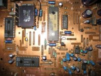
The PCB involved is an early Philips PCB marked "CMKS-81X" on the solder side. I think it dates from around 1989. I'm attempting to communicate with this module
using the I2C bus connected to a PIC device.
The problem is lack of knowledge about the message format required by the Philips DAC module. For example, I would like to know how to select a particular track, using the I2C bus, so I can progam the microcontroller to do this on demand.
The golden PCB contains the following chips: TDA1541A, SAA7220P, SAA7210, MAB8441, MN4264P and two LM833Ns.
If anyone has any information on this PCB, or knows where I can find it, please let me know!
Regards,
ramchip
ramchip said:The PCB involved is an early Philips PCB marked "CMKS-81X" on the solder side. I think it dates from around 1989. I'm attempting to communicate with this module
using the I2C bus connected to a PIC device.
The problem is lack of knowledge about the message format required by the Philips DAC module. For example, I would like to know how to select a particular track, using the I2C bus, so I can progam the microcontroller to do this on demand.
The golden PCB contains the following chips: TDA1541A, SAA7220P, SAA7210, MAB8441, MN4264P and two LM833Ns.
Regards,
ramchip
Sounds like a pcb from a cd player, not a dac module. 7210 is a decoder. Take a service manual from any philips/marantz player from that era for more details. As for the particular pcb, guess it is trail and error looking into manuals. CD106/650 come close, but have TDA1541 without A.
However, i never saw any info on the communication between the controllers in such a manual.
The MAB on your pcb would instruct the TDA89xx chips on a separate PCB, connected to a cdm drive (cdm2 or 4/31). How did you intend to inject the music datastream???
Thanks for your reply guido. I called it a DAC module for want of a better name. Maybe DAC system PCB is more accurate. All I have found so far is an overview
of the circuit in the SAA7220 datasheet, page 19. The SAA7210 is called A-chip, the SAA7220 is called B-chip and the TDA1541 is the DAC. I believe the PCB is similar to the one found in the Grundig 9000 player, as I saw
a photo on the Lampizator's website.
Anyway, I know the information I seek is more than I will find in any service manual.
I'm looking for the design manual that goes with this "DAC system PCB", if such a document exists.
Actually, the PCB is part of an old jukebox so the original designers must have had access to the I2C bus message formats that were necessary to make it work.
If I could find that information the problem would be solved!
The DAC system PCB connects to a cdm drive via ribbon cables. The audio signal comes from connectors on the DAC system PCB. I suppose if it turns out that the message format is proprietary to Philips then I will have reached a dead end. In the meantime I shall remain optimistic!
Regards,
ramchip
You can no more select a track by talking to the module than you can move the tonearm by moving the phonostage. The module or a control unit talks to the disc mechanism and it moves the laser accordingly.
I am trying to communicate with the control unit via the I2C bus. There is a connector on the PCB specifically for this bus and that's how the control unit is addressed in the machine. So far I can see messages on the bus which show the idle state and the play state, using a bus trace program I adapted for the PIC.
I know for a fact that the track selection for this machine is done using the I2C bus. What's not clear, at the moment, is the message format for track selection. Any help with how this is done would be much appreciated. Hopefully, someone might know about the CMKS-81X circuit board and it's mode of operation.
Regards,
ramchip
If you have the cd mechanism, then you have the model mumber and from there you can get more information.
Get a philips/marantz player from that time with multiple controllers. e.g. philips cd650. Good chance they all use the same communication protocol between display/keys and main controller.
Reversed engineering
Reversed engineering
Thanks for replies. Maybe a service manual for the Grundig CD-9000 player would help, as it contains a PCB very similar to the one I have.
I've just finished a Google sesssion looking for this manual without success.
Does anyone know of a source for this service manual?
Regards,
ramchip
I've just finished a Google sesssion looking for this manual without success.
Does anyone know of a source for this service manual?
Regards,
ramchip
ramchip said:......
Hope this helps!
Hi.
Can you post a photo of the whole board rather than just a portion ?
Thanks.
Andy
The heatsink on the MAB controller 😕
It's the 1541 that get's hot (and the 7220)
Weird.
As for your pcb, it looks a lot like one i took out of an aristona cd1006, which would be philips cd106. Only there the old chipset is used; 7220A and 1541 without A. PCB looks similar, only some components differ or are fitted/not fitted.
Transport there was a cdm2. Maybe your's uses cdm4/31.
The connector to the display/keyboard pcb (upper left in your picture) is 5 pins, right?
coding on pcb is 8204 055 01073 (guessing april 82)
The image is only missing a couple of cm at the top and few more to the right. At the top there are ribbon cable connectors to the CDM and the PSU. At the right there are PSU parts (regulators and capacitors) and the audio output connectors.
There ought to be enough detail here to identify the PCB, the chip layout and orientation are usually sufficient. In addition the PCB serial numbers are as follows:
Component side: 3104 103 34454 and 8204 055 01063
Solder side: 3104 103 34454 and 8204 055 01073
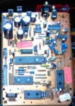
On the Grundig CD-9000 version of this PCB the last three digits are different so it's quite close. My version doesn't have the PCB headers near the LM833Ns
like the Grundig board, so fewer options are used.
I've included a shot of the Grundig PCB cropped from the Lampizator's photo of that machine (- thanks Lukasz).
There are probably quite a few early Philips CD players with this PCB so if anyone has a service manual with details of this board it would be great to hear from you!
Just seen new postings. The CDM is at the end of the ribbon cable and is working fine so there's no need to disturb it.
Guido! The PCB serial number you quote matches my solder-side number!
The connector in the upper left of my original picture is the I2C bus connector. This is the one I'm monitoring and looking for the CD track number, but so far that has not been successful. Was that connector used in the Aristona cd1006/Philips cd106?
Regards,
ramchip
There ought to be enough detail here to identify the PCB, the chip layout and orientation are usually sufficient. In addition the PCB serial numbers are as follows:
Component side: 3104 103 34454 and 8204 055 01063
Solder side: 3104 103 34454 and 8204 055 01073
On the Grundig CD-9000 version of this PCB the last three digits are different so it's quite close. My version doesn't have the PCB headers near the LM833Ns
like the Grundig board, so fewer options are used.
I've included a shot of the Grundig PCB cropped from the Lampizator's photo of that machine (- thanks Lukasz).
There are probably quite a few early Philips CD players with this PCB so if anyone has a service manual with details of this board it would be great to hear from you!
Just seen new postings. The CDM is at the end of the ribbon cable and is working fine so there's no need to disturb it.
Guido! The PCB serial number you quote matches my solder-side number!
The connector in the upper left of my original picture is the I2C bus connector. This is the one I'm monitoring and looking for the CD track number, but so far that has not been successful. Was that connector used in the Aristona cd1006/Philips cd106?
Regards,
ramchip
Attachments
It's a Philips CD160.
I have the manual if you want any circuit info (paper not .pdf)
It is also similar to the Marantz CD273.
Andy
I have the manual if you want any circuit info (paper not .pdf)
It is also similar to the Marantz CD273.
Andy
The CD640 or CD660 is very similar.
You can download the service manuals here:
http://www.audioamp.kylos.pl/audio/...wdownload&cid=2&min=20&orderby=titleA&show=10
You can download the service manuals here:
http://www.audioamp.kylos.pl/audio/...wdownload&cid=2&min=20&orderby=titleA&show=10
Thanks for the link carawu - that was very interesting!
Thanks for the offer poynton, but I think I had it now, the CD640 is the same.
As suspected, the service manual has nothing about the details of I2C bus usage. I'll have to improve my bus monitor to have any hope of using a PIC to control the CD player.
Thanks again to all the diyAudio folks that have helped.
Regards,
ramchip
By taking it out of the aristona, i do not mean that it does not work anymore 😀 It still works on the workbench, pcb's and cdm just spread out. The keyboard pcb contains a motorola controller on the other side of i2c.
So i do have the pcb working and i do have a logic analyser just behind it..... What do you need to know exactly ?? Could have a look. Also have an i2c monitoring program on a pc, but i'm not shure it still works.
Btw, the only keys i have are the normal keys like stop and play etc. No number keys as it is a budget model So not cd track number...
So i do have the pcb working and i do have a logic analyser just behind it..... What do you need to know exactly ?? Could have a look. Also have an i2c monitoring program on a pc, but i'm not shure it still works.
Btw, the only keys i have are the normal keys like stop and play etc. No number keys as it is a budget model
So not cd track number...Hm...sounds like the old PC-programs for controlling cdmpro/cdm12 via i2s....
Anybody can share actual links...else I dig in the dust (=my HD).
Carsten
Anybody can share actual links...else I dig in the dust (=my HD).
Carsten
It's the i2c monitor & debugger from Jan Verhoeven from 1998. But i don't have the hardware at hand and i recall it did not work in my case. Long ago....
- Status
- Not open for further replies.
- Home
- Source & Line
- Digital Line Level
- Old Philips DAC module - info. required.