I completed refurbing an old Magnavox tube radio but am having trouble translating some of the old alignment instructions to modern digital test equipment.
First, it appears my assumption about the polarity references, ”high side” and “low side” are not positive and negative respectively because when I do so DC voltage readings are negative. Another term with regards to DC measurements is “Adjust for maximum deflection”. I can only assume they mean positive analog meter needle deflection. If that is the case then high is negative and low positive.
The real confusion is on the signal generator and oscilloscope settings. Again, the high/low side confusion; “Signal generator coupling-High side to ungrounded tube shield over FM Converter tube, low side to chassis”. High here would seem to have to be positive!
Then comes this. “Use frequency modulated signal with 60cycle modulation and 450KC sweep. Use 120cycle sawtooth voltage in scope for horizontal deflection. Signal generator frequency 10.7MC (unmod)”. What!?!?
I have a Rigol MSO5104 with built in signal generator that I think can do all this but I can’t make sense of these instructions.
Can anyone explain?
Thanks,
Jeff
Just to be sure: is the radio's chassis insulated from the mains?
The signal generator has to be coupled to the signal path via a very small capacitance, like that provided by putting a metal cylinder around the mixer tube. Logically the centre conductor of your signal generator has to be connected to the cylinder while the generator ground has to be connected to the radio's ground: the chassis.
Apparently the signal generator has to be set to 10.7 MHz carrier frequency, FM modulated by some low frequency with 225 kHz peak deviation (or 450 kHz?). The horizontal deflection of the scope has to be synchronized to the modulating signal. Does your scope have an X-Y mode?
The idea is probably that each position on the horizontal axis corresponds to a certain momentary IF frequency, so you can see on your scope what the IF frequency response looks like.
It isn't clear to me why the recommended modulating frequency is half the sawtooth frequency.
Some advice with respect to aligning tuners -- see if it works satisfactorily before adjusting any coils.
Usually a "Sams PhotoFact" has very clear-cut instructions, and there's a "Sam's" for every set made in the US from the spark-gap era.
Usually a "Sams PhotoFact" has very clear-cut instructions, and there's a "Sam's" for every set made in the US from the spark-gap era.
Thank you Marcel and Jack.
Using an isolation transformer, which I confirmed removes any potential from the chassis.
It is Sam’s Photo fact I am quoting from. And I simply don’t understand the instructions.
The radio does function except for the AFC but that’s a priject for another day. Part of this exercise is for learning purposes.
Specifically;
Is “high side” positive or negative?
I can setup my SG for FM 10.7Mhz, 60hz sine modulation. I get that. My SG has a Sweep function. Is that the 450khz sweep referred to, or what my SG calls “Deviation”? If so I’m out of luck as the upper deviation limit is 1khz. And how is it calling for a 60hz modulation and under the SG frequency column it says “Unmod”? Doesn’t that mean unmodulated?
Is the “120hz sawtooth voltage in scope for horizontal deflection” a second SG channel to a second scope channel for XY display? The Rigol does XY but very poorly until the impending firmware upgrade.
And lastly, any idea why when I connect my DVM as instructed I get negative voltage? How would one attain “maximum deflection” if an analog meter was reading negative voltage?
Thanks again.
Jeff
The cores that you have to adjust may be brittle and fixed with wax or so, so be careful not to damage anything.
That (unmod.) must be an obsolete way to say that the carrier frequency has to be 10.7 MHz. For decades, 10.7 MHz was by far the most common intermediate frequency for FM receivers, so it makes sense that the test signal has to have a 10.7 MHz carrier frequency.
I'm not sure if that "sweep" refers to the peak value of the change of the momentary frequency, which would nowadays be called the frequency deviation, or to the peak-to-peak change of the momentary frequency, so twice the frequency deviation. I would guess twice the frequency deviation.
If your signal generator only supports deviations up to 1 kHz, you will have to manually change the frequency and do separate measurements. That is, measure with an unmodulated signal at several frequencies from 10.7 MHz - 225 kHz up to 10.7 MHz + 225 kHz. You also don't need an X-Y function then.
With an analog meter, you could just swap the input wires and get maximum deflection for the most negative voltage.
I don't know what "high side" refers to. It often means that the LO frequency has to be higher than the RF frequency, but apparently that's not what is meant here.
Last edited:
Ah, 60 years ago I knew this stuff.
You are aligning an IF strip? One thing itching in my mind is the band pass, which would have high and low frequency boundaries.
Unless otherwise noted, assume all voltage readings to be from ground.
Adjust for maximum deflection means peaking the circuit. Make whatever adjustments back and forth to maximize whatever the meter is showing. It really doesn't matter if we are working with positive or negative voltages, maximum is maximum. 20v is more than 10 v polarity aside.
High side. The output of your SG should be floating, not hard wired to ground. As an AC signal, RF has no polarity. I would be thinking high side means the hot wire from your SG and the low side would be the side normally grounded. Note in your instruction they mention connecting the high side to the ungrounded tube shield. This will couple the ssignal into the sensitive tube. The low side gets grounded to chassis.
In the old days, scopes could sweep freely or be triggered. Trigger reference could usually be set for 60Hz mains freq, or a sawtooth wave, or trigger off the signal.
Of course all this is speculation as we don't see the manual you refer to.
May I suggest using google. Enter "FM alignment procedure" and find all manner of useful information.
A web search for FM radio alignment was actually the first thing I did when I couldn’t make sense of the instructions. When I couldn’t correlate any modern instructions to the Photo Facts document, I came here.
I’d include a pic of the instructions but for the copyright issue. Not sure the Sams company is still in business but won’t take the chance.
But I have quoted most of the relevant instructions. The only other nebulous point is the SG output level “Use only enough generator output to provide a useable indication”. I tried everything from 20mv to 2v (5v is the upper limit of my scopes SG). The higher the output voltage, the LOWER the negative voltage reading (it approached 0 volts but never went positive). Suppose up to 5v would be safe?
Thanks all for the advice.
Jeff
The point is not to drive the IF chain into clipping. As long as the read-out is more or less proportional to the signal that you apply, it's apparently not yet clipping.
Jeff, you have quoted instructions, but we can't see the context, we can't see the circuit.
As to copyright, did you BUY the file from SAMS? If you found it online, then it is ALREADY out in the public. I'd call this "fair use". but do what you think best.
As to copyright, did you BUY the file from SAMS? If you found it online, then it is ALREADY out in the public. I'd call this "fair use". but do what you think best.
Sams is still in business and an excellent source for old manuals. I bought this manual from them a few years ago for $15.
I think you all have given me enough info to fill in some gaps and make more sense of this process. I actually got a scope trace that matches up well with the figure in the manual for one of the alignment steps. So I can’t be that far off.
The poor XY performance is a known glitch on the Rigol scope, said to be addressed in the next firmware. So that step will have to wait.
Jeff
I know this procedure as I built my own FM receiver in the seventies. All I can say: FM-strip alignment is very tricky, specially the ratio detector. There is a good chance things will get worse after screwing the coils. And btw I do not believe that the fx-generator of your scope will do as fm-modulated carrier generator. This is not something a beginner can do with the help of google.
Your right it doesn't do FM and I agree its not a simple matter .
OTOH --he could buy an old generator.
OTOH --he could buy an old generator.
Please review this data sheet on my scope. Scroll to near the bottom fir the Arbitrary Waveform Generator specs and tell me what you think.
https://beyondmeasure.rigoltech.com/acton/attachment/1579/f-0907/1/-/-/-/-/MSO5000_datasheet.pdf
Thanks,
Jeff
https://beyondmeasure.rigoltech.com/acton/attachment/1579/f-0907/1/-/-/-/-/MSO5000_datasheet.pdf
Thanks,
Jeff
Sorry Jeff your link has a tracker on it .
An Arbitrary Waveform Generator is a digitally produced sine/square/triangle generator --an FM signal has a signal that is frequency modulated .
I have already looked at your oscilloscope,s specification .
An Arbitrary Waveform Generator is a digitally produced sine/square/triangle generator --an FM signal has a signal that is frequency modulated .
I have already looked at your oscilloscope,s specification .
I built some tuner kits years ago, and they generally came with all the parts, except the IF strip came already assembled and aligned. They didn't trust us to do it on our own.
Sorry Jeff your link has a tracker on it .
An Arbitrary Waveform Generator is a digitally produced sine/square/triangle generator --an FM signal has a signal that is frequency modulated .
I have already looked at your oscilloscope,s specification .
Duncan, if its not asking too much, could you tell me what I am misinterpreting about the FM capabilities? The modulation section is near the bottom.
Attachments
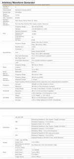
Where did you find that 1 kHz maximum deviation? I don't see it here.
The sweep function should also be usable, if you can synchronize the scope's time base with it.
The sweep function should also be usable, if you can synchronize the scope's time base with it.
Do NOT touch any of the aligning elements! This is the domain of experts that meanwhile die away. And btw - in my youth I fumbled with many radios and repaired some - screwing each coil available. At the end the error never was misalignment - but some failing parts like capacitors or resistors, switching contacts etc.
- Home
- Design & Build
- Equipment & Tools
- Old FM radio alignment procedure