Yes, definitely there is no third transformer.
The question is:
Will it be ok to add this voltage divider extra circuit at pin1 of controller ?
The question is:
Will it be ok to add this voltage divider extra circuit at pin1 of controller ?
After reading datasheet for dbl494 i found out that pin 3 is feedback.
http://html.alldatasheet.com/html-pdf/58383/DAEWOO/DBL494/365/2/DBL494.html
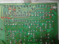
On PCB i traced the lines from controller pin 3 and marked the resistors (picture below).
If i am not wrong R22,R23 is feedback resistors that must be changed or R42 ?
http://html.alldatasheet.com/html-pdf/58383/DAEWOO/DBL494/365/2/DBL494.html
On PCB i traced the lines from controller pin 3 and marked the resistors (picture below).
If i am not wrong R22,R23 is feedback resistors that must be changed or R42 ?
Attachments
Last edited:
I've done this mod to an ATX power supply without the dedicated regulator and it works anyhow you've got nothing to lose here, old computer power supplies are cheap can easy to come by. 🙂
Best regards.
Best regards.
What Prohibition ? Are you kiding me ?
Many others have discussed about switching power supply electronics as i searched the forum before posting
It is not allowed to post about switching power supply ?
If there is a problem or prohibition moderator will say it not you.
I will decide the way and how to move on. If you don't like it move on yourself. As i said before ignore the post
FYI as long as the supply output is mains isolated its within the rules. If not, we close dangerous threads. That does not mean that other members concern should be taken the wrong way.

From the rules:
"While most projects on this site deal with electricity and construction which inherently involve some risk, particularly dangerous topics and procedures should include a warning in the thread that adequately explains these risks. Certain inherently dangerous topics are not allowed. At this time they include but are not limited to: discussing power supplies directly fed by mains current without a transformer, and mucking about in CRT video monitors."
Thank you Salas for posting the rules and what should not be posted on forum
I am sorry if i answered improper or in a wrong way.I am not new at electronics and didn't have in maind that i will get some answers regarding safety and rules.
It is just i am unfamiliar with switching power supplies and that's way i asked a little help with it.
About the PS:
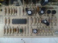
Today i had a little time to make some changes to my PS and did change the resistor from 12V rail to feedback as a friend above suggested.
The resistor is R40 and by increasing its value i did manage to get the desired 13,8 V BUT the PS oscillated as it did with first attempt i did with resistors at output rails.
Pictures at previous post in this thread could be useful to anyone that wants to help
If someone has anything more to suggest i would be happy to read.
I am sorry if i answered improper or in a wrong way.I am not new at electronics and didn't have in maind that i will get some answers regarding safety and rules.
It is just i am unfamiliar with switching power supplies and that's way i asked a little help with it.
About the PS:
Today i had a little time to make some changes to my PS and did change the resistor from 12V rail to feedback as a friend above suggested.
The resistor is R40 and by increasing its value i did manage to get the desired 13,8 V BUT the PS oscillated as it did with first attempt i did with resistors at output rails.
Pictures at previous post in this thread could be useful to anyone that wants to help
If someone has anything more to suggest i would be happy to read.
Although the rules note is old and states it very generally the key criterion is that the output should be mains isolated and everything mains side well insulated. A soft start circuit on the primary side of a big transformer in a power amp for example won't pass the mains to the secondary side and the loudspeaker outputs or chassis if it fails but all the insulation cautions should be there, and no inspection probing near it or maintenance should be performed when plugged to the wall. It could shock you when merrily probing around near circuits if not properly insulated & spaced for key parts, or arc, melt, and catch fire in case it fails on the field. The same stands for the SMPS that the VSSA guys popularly install which does have an isolation Tx in the middle as another example. While developing or testing/servicing, the best is to have a big mains isolation transformer for the AC line feeding all gear on a bench.
- Status
- Not open for further replies.
- Home
- Amplifiers
- Power Supplies
- Old Computer Power Supply Mod