Hi,
I have no doubt this is a Telefunken...but it looks like Chinese ****. Anyway i'm going to give tube rectification a try, just curiosity, my amp sounds good with the SS bridge.
I'm doing a hybrid bridge, see this;
http://www.lundahl.se/hybrid_pow.html
Some questions:
Would it be a good thing to bypass the diodes with 0.22 1000 V poly caps?
Am i going to lose many volts? Right now i'm using a full SS bridge and my B+ is 168V.
Maximun value for the first cap? Datasheet doesn't say.
Well, this is all, thanks in advance for the help.
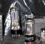
Oh, forgot to say,it's a AZ11.
Al.
I have no doubt this is a Telefunken...but it looks like Chinese ****. Anyway i'm going to give tube rectification a try, just curiosity, my amp sounds good with the SS bridge.
I'm doing a hybrid bridge, see this;
http://www.lundahl.se/hybrid_pow.html
Some questions:
Would it be a good thing to bypass the diodes with 0.22 1000 V poly caps?
Am i going to lose many volts? Right now i'm using a full SS bridge and my B+ is 168V.
Maximun value for the first cap? Datasheet doesn't say.
Well, this is all, thanks in advance for the help.
Oh, forgot to say,it's a AZ11.
Al.
Attachments
Hi Al,
why?
do you have seperate filament winding?
what is the az11?? a quick look on the web found az11 amd mother boad and a 1938 vintage full wave rectifier and no real info. you could loose some volts on B+
eg 5AR4 @ 225ma has about 17volts drop accross it at other conditions thi will be different.
http://www.pentalaboratories.com/pdfs/5ar4.pdf
bypass caps are a good thing, I would have chosen small value .047 but! depends what you want to acheive.
Robert
do you have seperate filament winding?
Yes.
what is the az11??
http://www.mif.pg.gda.pl/homepages/frank/sheets/076/a/AZ11.pdf
Anyway it looks like the leaning tower of Pissa, maybe an Italian would be interested in a swap?

Al.

stalker said:Hey moderators Pissa is an Italian city.
It' s "Pisa", one "s" only... 😀 😀
And lots of Italian towers lean. There are two in Bologna that used to be the same height, but one has been shortened to allow what remains not to collapse due to its inclination.
Hi Al,
maybe EC8010 could correct me but looking at the curves (my German is no existent!) depending on secondary resistance and load there would appear to be a fairly larg voltage drop accross the AZ11 over 44V at 100ma depending on Es, Is and Rs and you indicated your supply was 168v wont that lower your B+ too much?
the site I found had sod all info on the rectifier, interresting.
Robski666 said:Hi Al,
maybe EC8010 could correct me but looking at the curves (my German is non-existent!) depending on secondary resistance and load there would appear to be a fairly large voltage drop accross the AZ11 - over 44V at 100ma depending on Es, Is and Rs and you indicated your supply was 168v won't that lower your B+ too much?
Your confidence is flattering. I looked up the curves at Frank's site (was redirected to AZ1) but didn't know what current and reservoir capacitance to apply.
Hi EC8010, Al,
On page 2 there is a graph with voltage and current curves in the top lh is some data which i can gleen 16uf, thats the only reference to a capactor value I can see.
Robert
On page 2 there is a graph with voltage and current curves in the top lh is some data which i can gleen 16uf, thats the only reference to a capactor value I can see.
Robert
Hi Robski666,
I'm using a 6W6 for the moment, i used to have a 6AS7, but this one to my ears sounds best.
The 6W6 is a high current, low voltage tube. Right now, with 153 V at the plate and 44mA of current dissipates about 6 Watts (maximum for this tube is 10 Watts) , haven't measured the power output but guess is around 2 Watts (triode connected) more than enough with my 97 dB driver. The 6W6 datasheet says that with 110V at the plate and a current of about 50mA will put out 2.1 dissipating less than 6 Watts. This pentode connected.
Now i have two choices, leave it as a pentode and use it as a guitar amp or still use it as a triode raising the current to 80mA, dissipating about 8 Watts. My problem is i don't know the maximun current for this tube, datasheet doesn't say.
🙁
16 uF?
Quite low, right now with 47uF-330R-47uF-6.8K R- 100uF i have a little of hum. Doesn't bother me, didn't even tried grounding the filaments. With 16 uF i probably will need to buy a choke. No problem...will see.
Thank you guys, you've been helpful. I'll try 80mA and watch the tube, i have learned that they show strange colors when overstressed.
Al.
depending on secondary resistance and load there would appear to be a fairly larg voltage drop accross the AZ11 over 44V at 100ma depending on Es, Is and Rs and you indicated your supply was 168v wont that lower your B+ too much?
I'm using a 6W6 for the moment, i used to have a 6AS7, but this one to my ears sounds best.
The 6W6 is a high current, low voltage tube. Right now, with 153 V at the plate and 44mA of current dissipates about 6 Watts (maximum for this tube is 10 Watts) , haven't measured the power output but guess is around 2 Watts (triode connected) more than enough with my 97 dB driver. The 6W6 datasheet says that with 110V at the plate and a current of about 50mA will put out 2.1 dissipating less than 6 Watts. This pentode connected.
Now i have two choices, leave it as a pentode and use it as a guitar amp or still use it as a triode raising the current to 80mA, dissipating about 8 Watts. My problem is i don't know the maximun current for this tube, datasheet doesn't say.
🙁
16 uF?
Quite low, right now with 47uF-330R-47uF-6.8K R- 100uF i have a little of hum. Doesn't bother me, didn't even tried grounding the filaments. With 16 uF i probably will need to buy a choke. No problem...will see.
Thank you guys, you've been helpful. I'll try 80mA and watch the tube, i have learned that they show strange colors when overstressed.
Al.
Hi Al,
a quick search shows a different specs
http://www.nj7p.org/Tube1.php?tube=6w6
Anode I 47ma
6w6 info
Anode I 60ma
as for running the tubes at max plate disapation keep in mind a dull cherry red colour is sort of ok but there is a fine line between dull cherry red and too much heat disapation. the anode has sod all thermal mass and doesn't take a lot of power to raise its tempreture.
maybe it's time for a new project ;o) I see there is a "Nelson Pass 15w set amp" project on the forum here.
Robert
Ok, thanks Robski, anyway i've just decided to leave it as it is. Sounds great, this 6W6 triode connected. The AZ11 will fit nicely in a guitar amp project i have in my mind.
Thanks for your help.
Al.
Thanks for your help.
Al.
'Am I going to lose many volts'
If so, then the bypass capacitors would blow up as the capacitors would be absorbing energy and building up large amounts of heat.
The power supply would not lose any voltage using bypassing to protect the diodes from spikes. The rectifier tube will dominate the circuit sonically.
If so, then the bypass capacitors would blow up as the capacitors would be absorbing energy and building up large amounts of heat.
The power supply would not lose any voltage using bypassing to protect the diodes from spikes. The rectifier tube will dominate the circuit sonically.
Opps
I misread your question- 'lose many volts'. When changing from SS to a tube rectifier, some additional voltage drop will result. It depends upon the tube & currect draw thru the rectifier.
Cathode based rectifiers drop less volts than open filament types. Cathode type rectifiers I like are Mullard EZ80, Mullard EZ81 or Mullard GZ34. The Mullards consistantly provide the best sonics per my tests.
In your application, the Mullard GZ34 will provide the current capacity required.
Hi Amperex,
I have always wondered... you wrote about diferrent rectifiers sounds and i agree but it's just a matter of resistance, i think. When your B+ changes your plate impedance changes as well and the sound, of course, changes. I guess it's a matter of trying different ones in each circuit.
I already regret buying the AZ11; quite difficult to find a 8 DIN socket and it only takes 100mA of current... maybe good for a guitar amplifier if you want sag to be a factor in the final sound.
Guess you're going to post your impressions about the amps you're building once you finish them. I'm interested; 6550 PP sounds great, so i am told; but the big SE, in my humble opinion, should be the winner.
Al.
- Status
- Not open for further replies.
- Home
- Amplifiers
- Tubes / Valves
- Oh man, my telefunken stoops...