Why do we sometimes use an offset driver entry? And whats so significant about that location if its deliberate?
A few i use for an excuse to do it:
- the void at 3 x the Fb in the ‘TL’ is eliminated and a clear BW exists to the next void at the 5 /4 harmonic?
- that area created is often a fold and it simplifies driver entry?
- the area around the driver is often one that damping is bu e to use in and the offset driver makes it more affective as a lower pressure zone(more velocity to aid in the affective ness of any fibrous material used?
- more volume of enclosure might help acoustically and as a LPF?
But what else? I Find recently (it seems) if we do it on both sides of the cone it becomes an opportunity?!! As in the newer ‘PH’ modes of horn response. Theres a seriously powerful element in a ‘sacrificial anode’ rear chamber with an offset and stuffing strategically placed there.
What other ways is ‘offset’ used or useful that might be good to use or try and incorporate in a ‘design’?
Smooths response = less damping required = greater acoustic efficiency is the original reason around here, then the BWAC and for filling in the third harmonic dip in various horn designs.
Now its being used on both sides of the cone and the barn burner is engulfed in harmonic flames 🙂 Im lost in a never ending node at exit. phase aligned or something? Whatever it is its ‘special’. But i dunno what it is
Well, isn't that fundamentally the same as the 1/4 - 3/4 BAWC except in odd harmonics?
Yes, I think that is precisely that 🙂!?
...and folded (and driver entry at such locations) all wrapped up in a ‘pipe’ size that suits Vas per horn response. Then the CSA changes at the ‘antinode’ (it seems) to either support an out put gain or the lower ends extension(also at a fold) .
—— also(experimentally)—-The strategically placed damping material drags that low end into infrasonic obsurd to which i had to upgrade equipment and electrical to keep up with and the rabbit hole is a fountain.... and find 8 hz material(?)
But besides the last paragraph^^, the entire thing seems all to easy, yet i (WE)
Lots of people, have been so close over and over lots of times. Now its right there(not folded) in a sim. But add the folding and it(???? ) i dunno? But what am i listening to i dunno either, these tjings are brutal! Its amazing, but its tearing the place(home) apart, and the suv(car) apart and (however its tuned or biased)!
Im
Pinging on the 3/4 oid in sim. BUT in folding whats happening? I dunno, but its 5 seperate pipes affectively 2 only ‘bounce’ a pressure wave. The rest are time of flight and interconnect to a common exit
Last edited:
Is ‘offset’ a bell crank or cantilever?
In proper proportion we are sitting on a cycle and a 3rd of the other(if two pipes seperated by 90 degrees at exit?)
is this the ‘perfect pipe(s) or is always has been?
Why can i fold or expand or reduce csa at the antinode? Why does it ‘want to do that?’
The idea of a ‘horn’ is awesome, but impossible... however, the ‘pipe’ can take an expanded pipe or reduction pipe. Especially around the pressure antinode??!??
That seems vague, but you find it in horn response by default. Theres a limit of red S and pipe sectioms to use. Coincidence, or reality if in phase? Why is it always ‘good’ if not way better... cause it is(always)?
Last edited:
Why is earth(1.0 pi) to venus (0.71 pi) and mercury (0.4pi) and mars (1.6 pi)
And to jupiter (5.236 pi) and saturn (10pi).
When jupiter (48) and saturn (96) are to mars (12) when earth is 9. Venus 3 and mercury 1.5..
Ceres, btw, 2.8/24(?)
Pi/6 @3.1416 in 360 degrees is 2 pi R. (.5236 or 30 degrees) . In distance/angle/arc/etc. Why then is it also applicable to the speed and distance of orbit in the sky at 10x that same harmonic?
An eclipse shows this all too well. But if all the planets aligned in an eclipse we see the inside of a qw pipe. Unwrapped phase in aligned as two pipes.
Thats why they wanted ‘pluto’ to be something. But it only lasted til 2006... then it ran out of excuses... now its important to note mercury is in and out of that( 0.4 ) the sun is part of in sessions at a nuclear level. Its not even where it was just a short time ago...?
What jupiter is to a ‘ qw pipe’ is the 3/4 harmonic of a rear pipes Fb on a driver with a front pipe thats Fb is a 1/4 of a 4/4. and a rear joined at exit in perfect phase. I guess thats the 5/4 harmoinc of the front pipe, but my head hurts (hertz), lol? Hence the torrid meteor belt in june and October from its approach to earth and appearance as jupiter. But, Its much much more than that. And you can hear it in a speaker designed as such. Unfortunately for us that meteor belt has had an impact over the last few billion years and will continue to.. i wonder what hides in a qwpipe designed like this? The answers to a solar system /‘such as ours? I dont have a clue, but maybe someday somehow someone might?
Last edited:
^^^ that sounds kinda silly... i agree.
But is it that way just because thats reality? A universal reality of the maths? And thus makes sense if it ‘works’ in a qw pipe we can hear? I dunno, but regardless:
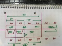
But play with 120cm as L23 and run it up through 150,160,190cm and loook at phase? A 10cm L45 is another tighter nit grouping higher up as well? See what you think as a hoqw enclosure? This is my original (year old or so) paraflex, with another driver added and the CSA increasd in the longside (front output).
But is it that way just because thats reality? A universal reality of the maths? And thus makes sense if it ‘works’ in a qw pipe we can hear? I dunno, but regardless:
But play with 120cm as L23 and run it up through 150,160,190cm and loook at phase? A 10cm L45 is another tighter nit grouping higher up as well? See what you think as a hoqw enclosure? This is my original (year old or so) paraflex, with another driver added and the CSA increasd in the longside (front output).
Attachments
Last edited:
My point: (assumes there is one, lol!)
Bets on this built to spec and not at ‘advanced centerline’ or any other methods of ? Pressure phase doesnt care about advanced centerlines or much of anything. Its reflected or its out the exit.? Not anythjng else except ‘head loss’ etc(nothing)
Bets on this built to spec and not at ‘advanced centerline’ or any other methods of ? Pressure phase doesnt care about advanced centerlines or much of anything. Its reflected or its out the exit.? Not anythjng else except ‘head loss’ etc(nothing)
Attachments
Last edited:
Is ‘offset’ a bell crank or cantilever?
Cantilever as in MJK's plucking a ruler, so if you want to calc the driver, vent offsets or bends even more accurately than MJK's 2D, then use cantilever beam math with actual cab/pipe i.d. dims for 3D like Altec suggested back circa '70.
Not quite sure how to respond to the rest, especially with this sinus/mouth/eyes infection that's making it hard read/type, much less think clearly and can't recall if I mentioned that with tight bends the wave breaks down into individual resonators due to impedance mismatches as the pipe/bend area becomes large enough WRT the WL and why they must always be expanding in a horn. Most folded horns are just a collection of resonant cavities/pipes and look like it in a measurement unless heavily smoothed. Fortunately our hearing acuity takes a dive below ~250 Hz, so a good place for BSC. 😉
This is why Olson made most of his 20 Hz BLH as a tiny expansion, only abruptly opening it up when the wave was mostly formed, i.e. basically a water basin feed system in reverse: US2224919A - Loud-speaker
- Google Patents
The more I studied the audio pioneers the more I found they were just standing on the shoulders of the real pioneers.
The water basin! 😀 I say, ‘draining the bathtub bass’, to my son(his massloaded tapered shape). instead of evaporating the water as steam, the step in expsbsion to exit the paraflex, lol??!
Cant decide which is better, but cannot give up the deep lows of the ‘polished up
Bass reflex air mass/spring( ie: mltl. Vs the absolute kick to the kick coming out of the paraflex that lacks down low by comparison but leaves nothing tto want as a result of what it does up a bit higher.
Everything seems to help here. And polishing this up in phase is all
There ever was wrong, but boy did it have a ‘weird’ side prior to recently and its easy to see why when guessing the combo exit location shAred and seperated by two pipes, until now. Its 3 distinct pipes and the exit is only a point of interest to a reference?? At the frequency the length of the rear sides pipe, the CSA change in the long pipe is now a reverse of Nodes affectively? Because its also an exact back and front wave?? This is unique, no?
- Home
- Loudspeakers
- Subwoofers
- Offset driver entry (the ‘upstream ‘pipe’)why?