Wondering if anyone knows the proper way to dial in the offset and bias on these units. I know that, when the amp is still cold, I'm aiming for ~0mv offset and 1.5mv bias.
That being said, the schematic isn't terribly clear where I am to measure for bias and offset. I can only assume it's the pairs of pins marked TP2 "Offset" and TP3 "Bias". I'm not sure what the TP1 "DC DET IN" is for...
Also when I measure across the offset pins and turn the amp on, I get a large initial value that slowly decreases over the next minute or two, and never stops fluctuating. Is this normal? Does that mean I should let the amp warm a little before performing the adjustment? Or is this just a consequence of my using a cheap multimeter?
Attachments
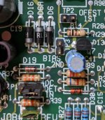
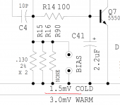
So it looks like the measurement process indeed involves taking offset at TP2 pins, and taking bias at TP3. Ashly stated they adjusted bias by measuring current between the HV DC rail and the amplifier board, and that they recommend I follow the schematics instructions of measuring via voltage at TP3.
One thing I'm still unclear on is: if I get close to ~0mV at the offset pins, and then plug my meter's leads in to the speaker taps, I get a small 2mv offset. I asked Ashly why offset is zeroed relative to the pins instead of the taps, and the answer was "Difference between offset at the diff-amp stage Vs the output stage"
I'd love to understand what this means and why zeroing at the differential stage is preferable to zeroing at the output stage(?).
...offset..., I get a large initial value that slowly decreases over the next minute or two, and never stops fluctuating. .....using a cheap multimeter?
Large like 100 Volts? Decreases to 5V or to 5mV? Does this "cheap multimeter" fluctuate reading a battery?
I got a 4.5 digit Tektronix bench meter help get a better handle on things.
With the leads on the VR2 "offset" pins, after switching on power I get around 40mV, with a steady drop to ~0mV over 70 seconds. Afterwards the reading fluctuates up and down by up to 1 or so mV.
When reading across the bias pins I always get a stable reading around what I adjusted it to.
At this point I'm mostly wondering why the offset adjustment process leaves some miniscule amount of DC at output.
Here are some quick rules of thumb:
- Offset measured at the speaker terminals after the amp is warmed up should be in the range of +/- 10mV
- Bias is best measured by inserting a meter in line with the positive power supply rail. Set the meter for 500mA range or so. Then set the BIAS for the amp for 420 mA draw at idle. Why? 20mA budget for the VAS and input stage. 4 X 100mA for the output stage.
Good luck.
Yes millivolts. Haha I suppose it's not worth fussing over now that I know my readings are reliable.
@Vilfort: IIRC Ashly said they, when measuring inline between supply and amp, aimed for 150mA of bias. That'd indeed be the ideal way to do it, and my meter could measure that current reliably, but I don't have the tool needed to disconnect the positive supply lead from the large connector housing used. As such, I'll trust that voltage measured at the "Bias" pins is reflective of the proper current per the schematics.
@Vilfort: IIRC Ashly said they, when measuring inline between supply and amp, aimed for 150mA of bias. That'd indeed be the ideal way to do it, and my meter could measure that current reliably, but I don't have the tool needed to disconnect the positive supply lead from the large connector housing used. As such, I'll trust that voltage measured at the "Bias" pins is reflective of the proper current per the schematics.
Attachments
Do as you please. I have built lots of amplifiers with Hitachi/Renesas MOSFETs and in my experience 150mA for 4 MOSFETs is simply too low. Good luck.
- Home
- Amplifiers
- Solid State
- Offset & Bias on an Ashly FTX-2001 Series 3