schematic error
My apologies,
You are both right, the schematic is drawn wrong the two caps should be in series with the resistors R7 & R8 and connected across the gate drive transformer after the 10 ohm resistors in series with the IGBT gate. Note: This added filter might not be needed in all designs.
chas1
My apologies,
You are both right, the schematic is drawn wrong the two caps should be in series with the resistors R7 & R8 and connected across the gate drive transformer after the 10 ohm resistors in series with the IGBT gate. Note: This added filter might not be needed in all designs.
chas1
230V step down
I havent read all 11 pages, but if I was new to OFFLINE SMPS design, I would first consider designing a FLYBACK power supply to perform some experimenting, and learn about DCM, CCM, Snubbers, high voltage trace circuit layout.
I would then modify the above FLYBACK SMPS so that it has an ISOLATED feedback circuit using either an opamp or everyone's favorite TL431 shunt regulator.
Once I have designed, built, tested, and simulated a working Flyback converter,
I would design a 2 Transistor Forward converter, the Highside NFET could either be driven by a MOSFET gate drive IC, or better yet, by a transformer.
Even better would be a 1:1:1 transformer with good isolation so that the PWM IC can drive the low and highside MOSFETS through the transformer.
The 2 Transistor forward converter has easy to design magnetics, almost easy enough to wind by hand transformer, medium voltage MOSFETS, and the design is far safer since the fets are in series with the power transformer primary.
I would use the opto-isolated feedback on 2T forward converter as well.
Nejc_car said:Is it posible to build a push-pull smps for 230Vac.
I havent read all 11 pages, but if I was new to OFFLINE SMPS design, I would first consider designing a FLYBACK power supply to perform some experimenting, and learn about DCM, CCM, Snubbers, high voltage trace circuit layout.
I would then modify the above FLYBACK SMPS so that it has an ISOLATED feedback circuit using either an opamp or everyone's favorite TL431 shunt regulator.
Once I have designed, built, tested, and simulated a working Flyback converter,
I would design a 2 Transistor Forward converter, the Highside NFET could either be driven by a MOSFET gate drive IC, or better yet, by a transformer.
Even better would be a 1:1:1 transformer with good isolation so that the PWM IC can drive the low and highside MOSFETS through the transformer.
The 2 Transistor forward converter has easy to design magnetics, almost easy enough to wind by hand transformer, medium voltage MOSFETS, and the design is far safer since the fets are in series with the power transformer primary.
I would use the opto-isolated feedback on 2T forward converter as well.
Re: Re: gate drv (bad design)???
I'm confused by the need for GDRVRET in this schematic. Why can't GDRVET be disconnected from the PWM IC and the gate drive transformer be tied to ground?
Also, C12 looks like a mistake.
Also, what is the advantage of using IGBT's in this circuit, vs MOSFETS, is it just for their voltage rating, or do IGBTS tend to produce cleaner switches? Isn't the "Current Tail" a problem when switching high current quickly?
Also, what is the advantage of a current sense winding + bridge rectifier over the typical resistor in series with the low side switch to ground?
mzzj said:
ARE WE talking about same thing?
http://www.diyaudio.com/forums/attachment.php?s=&postid=1250579&stamp=1183807698
Crown definetely doesn't use gate drive like that in Pulse series, and TI's focus.ti.com/lit/ml/slup083/slup083.pdf paper doesnt show it either. In Chacal's schematic move C12 to the left side of R7 so that it is in series with R6 and its fine.
😡
I'm confused by the need for GDRVRET in this schematic. Why can't GDRVET be disconnected from the PWM IC and the gate drive transformer be tied to ground?
Also, C12 looks like a mistake.
Also, what is the advantage of using IGBT's in this circuit, vs MOSFETS, is it just for their voltage rating, or do IGBTS tend to produce cleaner switches? Isn't the "Current Tail" a problem when switching high current quickly?
Also, what is the advantage of a current sense winding + bridge rectifier over the typical resistor in series with the low side switch to ground?
luka said:Hi
This is for you Steve and others, I think it is not bad for second version 🙂
pcb file found ?
Re: Re: Re: gate drv (bad design)???
Location of C12 is a mistake, thats what we have been talking about here.
IGBT's: lower price mainly. Current tail is small or neglible problem with modern IGBT's designed for SMPS use.
Current transformer: lower power dissipation with high currents. And added isolation and noise immunity.
because same pulse transformer drives 2 different switches with opposite phasing in bipolar-style.(hope you get my explanation)davefromnj said:
I'm confused by the need for GDRVRET in this schematic. Why can't GDRVET be disconnected from the PWM IC and the gate drive transformer be tied to ground?
Also, C12 looks like a mistake.
Also, what is the advantage of using IGBT's in this circuit, vs MOSFETS, is it just for their voltage rating, or do IGBTS tend to produce cleaner switches? Isn't the "Current Tail" a problem when switching high current quickly?
Also, what is the advantage of a current sense winding + bridge rectifier over the typical resistor in series with the low side switch to ground?
Location of C12 is a mistake, thats what we have been talking about here.
IGBT's: lower price mainly. Current tail is small or neglible problem with modern IGBT's designed for SMPS use.
Current transformer: lower power dissipation with high currents. And added isolation and noise immunity.
Thanks!
Thanks for the explanation!
Ah, I forgot it's a Half Bridge topology, so IGBT 1 and IGBT 2 are always driven 180degrees out of phase.
Are IGBT's really cheaper? I'll have to look into that.
Thanks for the explanation!
Ah, I forgot it's a Half Bridge topology, so IGBT 1 and IGBT 2 are always driven 180degrees out of phase.
Are IGBT's really cheaper? I'll have to look into that.
Current winding transformer
About how many turns would you typically use for a current winding transformer, compared to the Primary turns?
About how many turns would you typically use for a current winding transformer, compared to the Primary turns?
Dave,
Amplifying mzzj's comments a bit, a current-sense transformer (as opposed to a series-sense resistor in line with the lower switch) also enables true symmetric current-sensing. Popular winding ratios for a current-sense transformer are 50:1, 100:1, and 200:1, the one turn being the primary. Coilcraft and others make small molded toroids with two or three leads (for either full-bridge or center-tap rectification of the signal). Simply shoot the primary thru the center hole, and you're off to a good start.
Steve
In Full Bridge configuration using a common series resistor in lower rail of IGBT emitters also enables symmetric current sharing.......is'nt it ??
I have experienced, Half Bridge smps used to develop noise problems when subjected to varying frequency of generator say from 60hz to 30hz, meanwhile fullbridge has no probs of this sort at all....
Whats your views N-Channel.....
Whats your views N-Channel.....
N-Channel said:Dave,
Amplifying mzzj's comments a bit, a current-sense transformer (as opposed to a series-sense resistor in line with the lower switch) also enables true symmetric current-sensing. Popular winding ratios for a current-sense transformer are 50:1, 100:1, and 200:1, the one turn being the primary. Coilcraft and others make small molded toroids with two or three leads (for either full-bridge or center-tap rectification of the signal). Simply shoot the primary thru the center hole, and you're off to a good start.
Steve
A single current transformer in series with the primary may saturate during big load transients giving erratic measurements and sometimes inhibiting current limiting, this only works reasonably well with voltage mode and slowly varying loads (like in a PC power supply). A workaround for this is using two current transformers, one in each switching path. Peak current control may be implemented in half bridges that way.
Workhorse said:I have experienced, Half Bridge smps used to develop noise problems when subjected to varying frequency of generator say from 60hz to 30hz, meanwhile fullbridge has no probs of this sort at all....
Whats your views N-Channel.....
I'm not sure what you mean "60hz to 30hz". Are you talking about the output of a portable generator? If so, then I believe this would happen only when the gen-set sees a sudden load increase, and the gen-set momentarily dips in speed while trying to meet the sudden load increase. As for niose problems occuring in a HB when thisa occurs, I can't be cretian, but perhaps you could try bigger DC Bulk Caps to make up for the momentary lower frequency. Also, since, at 30Hz, even incandescent lights will start to flicker, this condition could be contributing to the noise problem as the frequency passes through a value that is a funcamental harmonic of your switcher's operating frequency.
Eva said:
A single current transformer in series with the primary may saturate during big load transients giving erratic measurements and sometimes inhibiting current limiting, this only works reasonably well with voltage mode and slowly varying loads (like in a PC power supply). A workaround for this is using two current transformers, one in each switching path. Peak current control may be implemented in half bridges that way.
I have heard of this technique, but never why. This is interesting, EVA.
Workhorse, If there were ever a danger of a sudden load inrease across the primary to the point of current xfmr saturation, I would definitely recommend trying EVA's approach, of stick with the series-sense resistor you describe regarding full-bridge.
N-Channel said:
I'm not sure what you mean "60hz to 30hz". Are you talking about the output of a portable generator? If so, then I believe this would happen only when the gen-set sees a sudden load increase, and the gen-set momentarily dips in speed while trying to meet the sudden load increase. As for niose problems occuring in a HB when thisa occurs, I can't be cretian, but perhaps you could try bigger DC Bulk Caps to make up for the momentary lower frequency. Also, since, at 30Hz, even incandescent lights will start to flicker, this condition could be contributing to the noise problem as the frequency passes through a value that is a funcamental harmonic of your switcher's operating frequency.
Workhorse, If there were ever a danger of a sudden load inrease across the primary to the point of current xfmr saturation, I would definitely recommend trying EVA's approach, of stick with the series-sense resistor you describe regarding full-bridge.
Yes the frequency output of generator sometimes drop or vary alot from 60 to 30 Hz. I have seen many HB SMPS amps which begin to noise when frequency drops but this isnot the case with FB smps........
I never used current xfmr approach, i relied on resistor approach in FB SMPS for symmetric current sensing. In my new project i am implementing Hall-effect current sensors from Allegro, they also provide isolation as well as the series element drop resistance is just 150micro Ohm.....so no losses.....
I so sorry. I design SMPS but I'm not yet in business, and given the SMPS migration that the PA market is experimenting, I can't provide such a ready-made schematic to you for free because I still expect to make some profit from my work before other people could start cloning and selling my prototypes like crazy
linbhunt said:I so sorry. I design SMPS but I'm not yet in business, and given the SMPS migration that the PA market is experimenting, I can't provide such a ready-made schematic to you for free because I still expect to make some profit from my work before other people could start cloning and selling my prototypes like crazy
Who are you and who told you to give smps schematic??

All finished
Hi
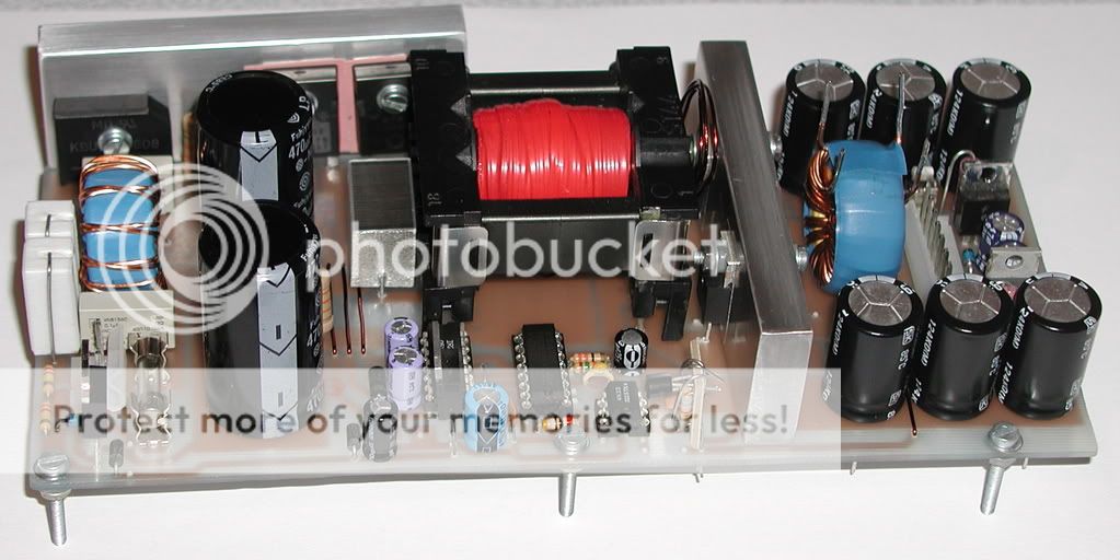
It is time to say that all is done, nothing more to be upgraded. I am posting my PCB and SCHEMATIC of offline/mains powered Half-Bridge supply.It is regulated, with main output voltages + 2 for +/-12V or whatever. Pcb was made for ETD44, but I didn't used it.
Here are the photos


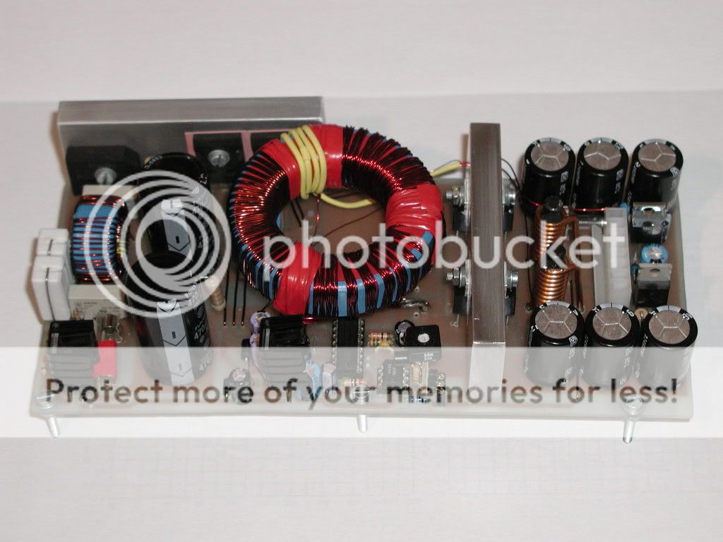
Enjoy and have fun with is, like I did
Here is first file...
Hi
It is time to say that all is done, nothing more to be upgraded. I am posting my PCB and SCHEMATIC of offline/mains powered Half-Bridge supply.It is regulated, with main output voltages + 2 for +/-12V or whatever. Pcb was made for ETD44, but I didn't used it.
Here are the photos
Enjoy and have fun with is, like I did
Here is first file...
Attachments
Someone's been busy. Luka, That is some very nice work. Couple o' questions: What happened to the E-E core Xfmr? Does the Toroid give better performance?
Also, I noticed that the two series resistors R15 & R16 are only 680W. When I briefly had my HB SG3525-controlled SMPS working, I used 2- 8.2kW 5-watters in series, this limiting the max current thru the TIP50 to ~25mA. During Start-up, do you notice these two resistors getting hot?
Other than those points, it looks really kick-a$$!
Hi
First of all I would like to thank you for all help that you gave me, also Chas1 and Eva + others too ofcourse... Big thanks to all
I didn't use it because it had big ratio(or in this case small(20:11,11)I would be better looking and better performing if ETD would be used, but I have rewinded that sucker so many times, that I couldn't do it once more and I wanted to see if toroids are any good (giving power, not with EMI) coz I have a lot of smaller ones, that I have no use for them yet...
R15 & R16: I know that is quiet low value, I would use 2.2k now, but they don't heat up, not one bit. Only Tip50 if there is no aux voltage from Xfmr.I had SMPS like that at first, to see how this works, Tip got hot (no heatsink), but after 10s of running that I think is more then normal. And such low value of resistors mean that SG and IR could be powered all the time from bulk caps, but with high losses.
To tell the truth, it is not as good as I want it to be, there could be current limiting, proper regulation (This one works, just I don't know how stable).... Basically new diffrent board that I don't have will to do one from start again for some time. Maybe I will do that for Battery charger....
Whole point of this design was to make it low, to fit it in 1HE or 4cm.
First of all I would like to thank you for all help that you gave me, also Chas1 and Eva + others too ofcourse... Big thanks to all
I didn't use it because it had big ratio(or in this case small(20:11,11)I would be better looking and better performing if ETD would be used, but I have rewinded that sucker so many times, that I couldn't do it once more
and I wanted to see if toroids are any good (giving power, not with EMI) coz I have a lot of smaller ones, that I have no use for them yet...R15 & R16: I know that is quiet low value, I would use 2.2k now, but they don't heat up, not one bit. Only Tip50 if there is no aux voltage from Xfmr.I had SMPS like that at first, to see how this works, Tip got hot (no heatsink), but after 10s of running that I think is more then normal. And such low value of resistors mean that SG and IR could be powered all the time from bulk caps, but with high losses.
To tell the truth, it is not as good as I want it to be, there could be current limiting, proper regulation (This one works, just I don't know how stable).... Basically new diffrent board that I don't have will to do one from start again for some time. Maybe I will do that for Battery charger....
Whole point of this design was to make it low, to fit it in 1HE or 4cm.
- Home
- Amplifiers
- Power Supplies
- Offline full-bridge SMPS… need help